Publication Cover
Mathematical and Computer Modelling of Dynamical Systems
Methods, Tools and Applications in Engineering and Related Sciences
Volume 19, 2013 - Issue 6
260
Views
3
CrossRef citations to date
0
Altmetric
Original Articles

Incremental optimal process excitation for online system identification based on evolving local model networks

, , &
Pages 505-525 | Received 14 Aug 2012, Accepted 23 Apr 2013, Published online: 22 May 2013

Figures & data

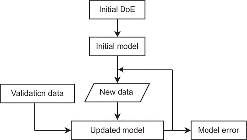
Figure 1. Generation of an optimal experiment design (OED) in an online procedure based on an evolving model.
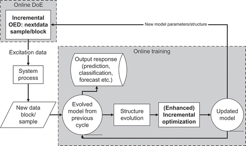
Figure 1. Generation of an optimal experiment design (OED) in an online procedure based on an evolving model.

Figure 2. Contour lines of the validity functions of a local model network with six local models. The partition space is spanned by and .
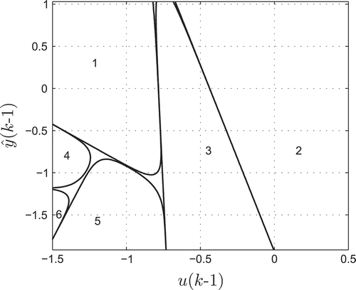
Figure 2. Contour lines of the validity functions of a local model network with six local models. The partition space is spanned by and .

Figure 3. Illustration of the hierarchical model trees for two and three local models.

Figure 3. Illustration of the hierarchical model trees for two and three local models.

Figure 4. Online optimization of future system inputs under constraints.

Figure 4. Online optimization of future system inputs under constraints.

Figure 5. Illustration of an intersection plot of the smoke model. The output is depicted in the unit of filter smoke number (FSN) for a fixed exhaust gas recirculation (EGR) rate, timing of main injection and timing of pilot injection.
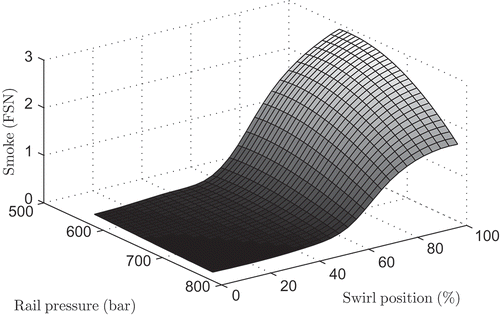
Figure 5. Illustration of an intersection plot of the smoke model. The output is depicted in the unit of filter smoke number (FSN) for a fixed exhaust gas recirculation (EGR) rate, timing of main injection and timing of pilot injection.

Figure 6. Comparison of normalized optimality criteria. The D criterion denotes the determinant of the Fisher information matrix and the D-S criterion denotes the hybrid criterion combining the determinant of the Fisher information matrix with a distance measure.
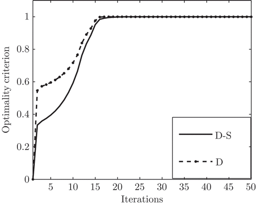
Figure 6. Comparison of normalized optimality criteria. The D criterion denotes the determinant of the Fisher information matrix and the D-S criterion denotes the hybrid criterion combining the determinant of the Fisher information matrix with a distance measure.

Table 1. Comparison of the number of design points for three particular model errors (MSE) and three experimental designs.

Figure 7. Schematic illustration of the model validation.

Figure 7. Schematic illustration of the model validation.

Figure 8. Illustration of the model quality in the form of the mean squared error (MSE) as a function of the sample size for the D-S-optimal design, the S-optimal design and the fullfactorial design.
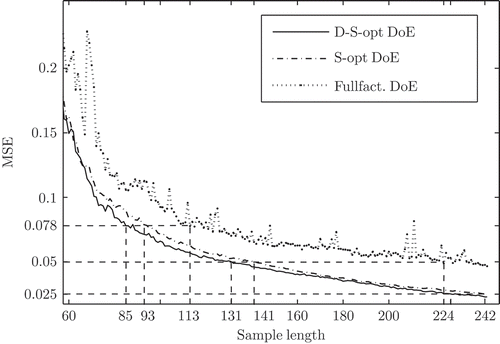
Figure 8. Illustration of the model quality in the form of the mean squared error (MSE) as a function of the sample size for the D-S-optimal design, the S-optimal design and the fullfactorial design.

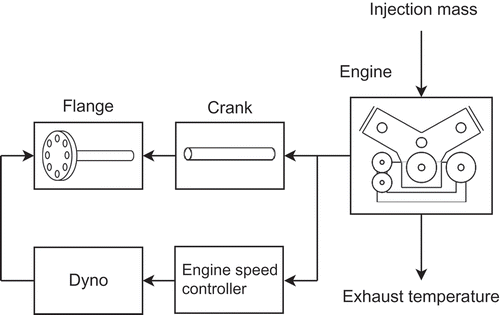
Figure 9. Engine with controlled engine speed.

Figure 9. Engine with controlled engine speed.

Figure 10. The upper part illustrates the design of experiments (DoE) given by the injection mass signal and the lower part indicates the associated system response (exhaust temperature). The snapshot is taken exactly when the initial DoE sequence (first 300 samples) is applied to the system. The outlook on the future model-based DoE (mDoE) ranges from the 301st to the 320th sample. For the future mDoE, the exhaust temperature is demanded to comply with the feasible range from 620K to 780K.
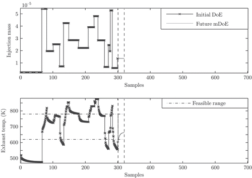
Figure 10. The upper part illustrates the design of experiments (DoE) given by the injection mass signal and the lower part indicates the associated system response (exhaust temperature). The snapshot is taken exactly when the initial DoE sequence (first 300 samples) is applied to the system. The outlook on the future model-based DoE (mDoE) ranges from the 301st to the 320th sample. For the future mDoE, the exhaust temperature is demanded to comply with the feasible range from 620K to 780K.

Figure 11. The upper part illustrates the design of experiments (DoE) given by the injection mass signal and the lower part indicates the associated system response (exhaust temperature). The snapshot of the DoE procedure has been taken after Figure 10 when 190 samples of the model-based DoE sequence (mDoE) have already been applied to the system. The applied mDoE sequence (301st to 490th sample, grey line) generates a system response that stays well within the feasible exhaust temperature range. The outlook on the future model-based DoE (solid black line) ranges from the 491st to the 510th sample.
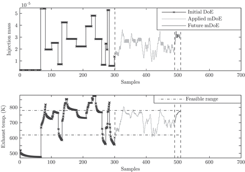
Figure 11. The upper part illustrates the design of experiments (DoE) given by the injection mass signal and the lower part indicates the associated system response (exhaust temperature). The snapshot of the DoE procedure has been taken after Figure 10 when 190 samples of the model-based DoE sequence (mDoE) have already been applied to the system. The applied mDoE sequence (301st to 490th sample, grey line) generates a system response that stays well within the feasible exhaust temperature range. The outlook on the future model-based DoE (solid black line) ranges from the 491st to the 510th sample.

Figure 12. The upper part illustrates the design of experiments (DoE) given by the injection mass signal and the lower part indicates the associated system response (exhaust temperature). The snapshot of the DoE procedure has been taken after Figure 11 when 380 samples of the model-based DoE (mDoE) sequence have already been applied to the system (301st to the 680th sample, grey line). The applied mDoE sequence generates a system response that stays well within the feasible exhaust temperature range. The outlook on the future model-based DoE (solid black line) ranges from the 681st to the 700th sample.
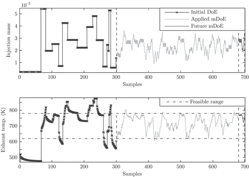
Figure 12. The upper part illustrates the design of experiments (DoE) given by the injection mass signal and the lower part indicates the associated system response (exhaust temperature). The snapshot of the DoE procedure has been taken after Figure 11 when 380 samples of the model-based DoE (mDoE) sequence have already been applied to the system (301st to the 680th sample, grey line). The applied mDoE sequence generates a system response that stays well within the feasible exhaust temperature range. The outlook on the future model-based DoE (solid black line) ranges from the 681st to the 700th sample.

Figure 13. Distribution of the exhaust temperature for the model-based design of experiments (mDoE) and the amplitude modulated pseudo random binary sequence (APRBS). The optimal excitation signal is generated with a minimal and a maximal exhaust temperature of 620K to 780K.
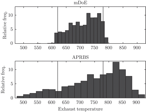
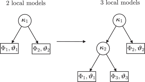
Figure 13. Distribution of the exhaust temperature for the model-based design of experiments (mDoE) and the amplitude modulated pseudo random binary sequence (APRBS). The optimal excitation signal is generated with a minimal and a maximal exhaust temperature of 620K to 780K.
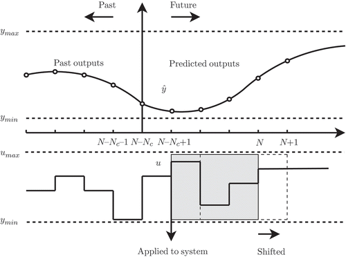
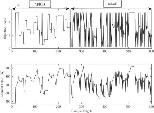
Figure 14. Exemplary illustration of the input and output validation data. The data consist of an amplitude modulated pseudo random binary sequence (APRBS) and of a model-based design of experiments (mDoE).

Figure 14. Exemplary illustration of the input and output validation data. The data consist of an amplitude modulated pseudo random binary sequence (APRBS) and of a model-based design of experiments (mDoE).

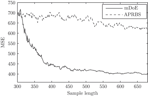
Figure 15. Development of the mean squared error (MSE) as a function of the sample length for the amplitude modulated pseudo random binary sequence (APRBS) and the model-based design of experiments (mDoE).

Figure 15. Development of the mean squared error (MSE) as a function of the sample length for the amplitude modulated pseudo random binary sequence (APRBS) and the model-based design of experiments (mDoE).

Reprints and Corporate Permissions

Please note: Selecting permissions does not provide access to the full text of the article, please see our help page How do I view content?

To request a reprint or corporate permissions for this article, please click on the relevant link below:

Academic Permissions

Please note: Selecting permissions does not provide access to the full text of the article, please see our help page How do I view content?

Obtain permissions instantly via Rightslink by clicking on the button below:

If you are unable to obtain permissions via Rightslink, please complete and submit this Permissions form. For more information, please visit our Permissions help page.