Publication Cover
Mathematical and Computer Modelling of Dynamical Systems
Methods, Tools and Applications in Engineering and Related Sciences
Volume 20, 2014 - Issue 4
343
Views
3
CrossRef citations to date
0
Altmetric
Original Articles

Model order reduction for numerical simulation of particle transport based on numerical integration approaches

Pages 317-344 | Received 29 Mar 2012, Accepted 22 Oct 2013, Published online: 05 Dec 2013

Figures & data

Figure 1. Modelling plasma reactors with linearization and splitting techniques.

Figure 1. Modelling plasma reactors with linearization and splitting techniques.

Table 1. Numerical errors of the linearization techniques 1)–4) for the non-linearity α=3.

Table 2. Numerical errors of the linearization techniques 5)–7) for the non-linearity α=3.

Figure 2. The numerical errors of the different linearization techniques.

Figure 2. The numerical errors of the different linearization techniques.

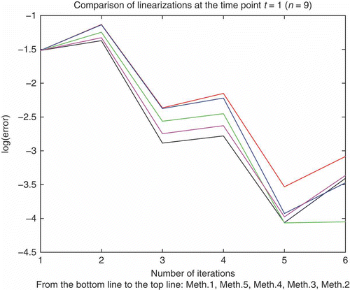
Table 3. Numerical errors of the linearization techniques 1)–4) for the non-linearity α=9.

Figure 3. The numerical errors of the different linearization techniques.

Figure 3. The numerical errors of the different linearization techniques.

Table 4. Numerical errors of the optimal linearization technique 4).

Table 5. Physical parameters.

Figure 4. x-axis: Time scale, y-axis: concentration, numerical solution and exact solution coincide in the same line.
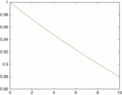
Figure 4. x-axis: Time scale, y-axis: concentration, numerical solution and exact solution coincide in the same line.

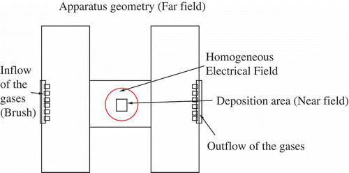
Figure 5. Spatial domain of the PE-CVD apparatus.

Figure 5. Spatial domain of the PE-CVD apparatus.

Table 6. Computed and experimental fitted parameters with UG simulations.

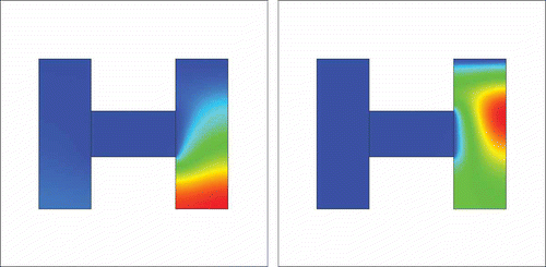
Figure 6. Two inflow sources xTi,yTi=(35,190) and xTi,yTi=(215,190) with perpendicular velocity and 100 time-steps, with the ratio between C and Ti equal to 3.6.
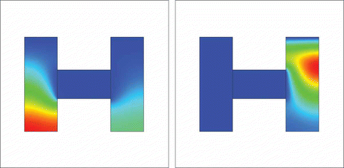
Figure 6. Two inflow sources xTi,yTi=(35,190) and xTi,yTi=(215,190) with perpendicular velocity and 100 time-steps, with the ratio between C and Ti equal to 3.6.

Figure 7. Two inflow sources xTi,yTi=(35,190) and xTi,yTi=(215,190) with perpendicular velocity and 150 time-steps, with the ratio between C and Ti equal to 3.6.
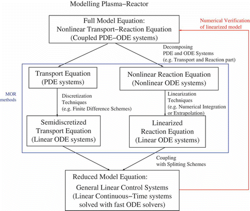
Figure 7. Two inflow sources xTi,yTi=(35,190) and xTi,yTi=(215,190) with perpendicular velocity and 150 time-steps, with the ratio between C and Ti equal to 3.6.
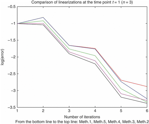
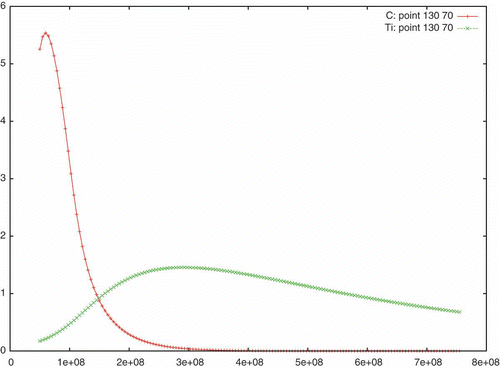
Figure 8. Deposition rates in the case of two point sources, = 35,215, = 190, with perpendicular velocity and 150 time-steps, with the ratio between C (+ line) and Ti (x line) equal to 3.6.

Figure 8. Deposition rates in the case of two point sources, x = 35,215, y = 190, with perpendicular velocity and 150 time-steps, with the ratio between C (+ line) and Ti (x line) equal to 3.6.

Reprints and Corporate Permissions

Please note: Selecting permissions does not provide access to the full text of the article, please see our help page How do I view content?

To request a reprint or corporate permissions for this article, please click on the relevant link below:

Academic Permissions

Please note: Selecting permissions does not provide access to the full text of the article, please see our help page How do I view content?

Obtain permissions instantly via Rightslink by clicking on the button below:

If you are unable to obtain permissions via Rightslink, please complete and submit this Permissions form. For more information, please visit our Permissions help page.