Figures & data
Figure 1. The considered 9-roll hot leveller with bending mechanism.
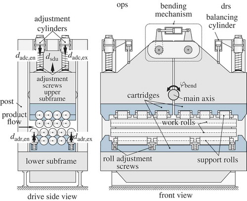
Figure 2. Configuration of rolls and coordinate systems.
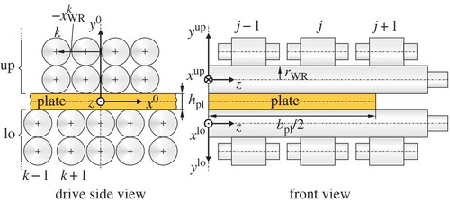
Figure 3. Top: configuration of work and support rolls. Bottom: line loads and approximated concentrated forces acting on the work roll with simplified geometry.
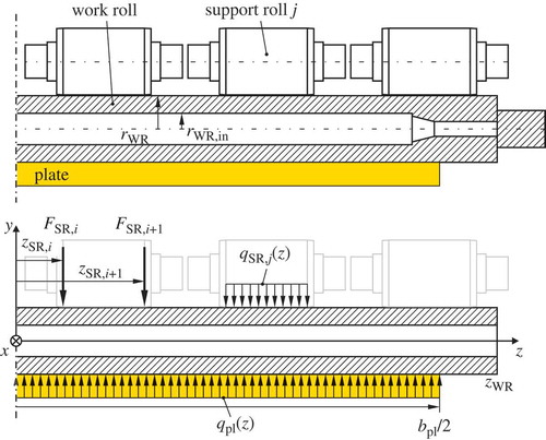
Figure 4. Reference position and position under load of a work roll in contact with a support roll.
Figure 5. Nonconforming contact under load and typical force–deflection characteristic of the real machine, cf. [Citation16].
![Figure 5. Nonconforming contact under load and typical force–deflection characteristic of the real machine, cf. [Citation16].](/cms/asset/13ee6ccb-9d16-4af2-9be0-77a62e1e21fa/nmcm_a_941881_f0005_b.gif)
Figure 6. Components of the upper subframe and cartridge used for the finite element model.
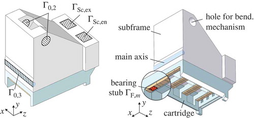
Figure 7. Configuration of posts and adjustment screws.
Figure 8. Normalized deflection contributions of the parts of the leveller frames to the deflection of the support roll edges.
Figure 9. Definition of the roll intermesh.
Figure 10. Principle of the deflection measurement with forceless supports inserted into a test plate.
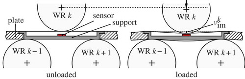
Figure 11. Support with mounted eddy-current sensor inserted into the test plate.
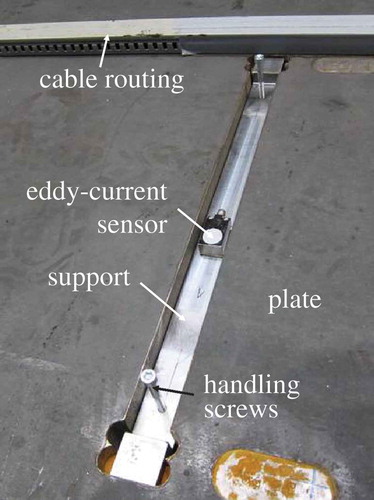
Figure 12. Wide test plate with the sensor placements relative to the work and support roll locations.
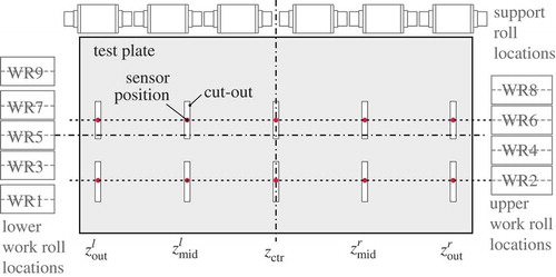
Figure 13. The wide test plate aligned in the considered leveller.
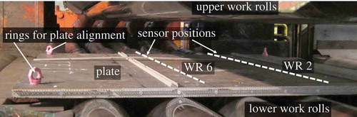
Figure 14. Measured roll intermesh for selected rolls over the mean adjustment and the measured total load force for the large test plate.
Table 1. List of load cases.
Figure 15. Comparison of measured and calculated roll intermesh difference.
Figure 16. Residuals of the model for the considered load cases of .