Figures & data
Figure 1. (a) The adaptive spindle support (CAD model) and (b) real component mounted on a parallel-kinematic machine [Citation14].
![Figure 1. (a) The adaptive spindle support (CAD model) and (b) real component mounted on a parallel-kinematic machine [Citation14].](/cms/asset/4d031e2b-b31c-4cd6-bd51-31a98dfe5f84/nmcm_a_1218347_f0001_oc.jpg)
Table 1. Balancing transformations for the second-order index-1 descriptor systems.
Table 2. The performances of the heuristic and adaptive shifts in Algorithm 5 for the ASS model.
Table 3. Balancing on different levels and to different dimensional ROMs.
Figure 2. Comparison of original and different dimensional reduced systems (dimensions indicated in the legend) computed by Algorithm 2.
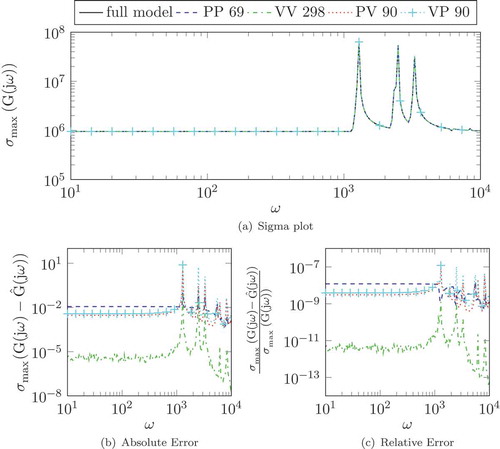
Figure 3. Relative error of full and different dimensional reduced systems (dimensions indicated in the legend) via balancing the system on the position level.
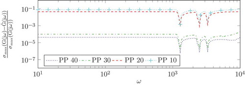
Figure 4. Eigenvalue structures of the different dimensional reduced models obtained by position–position balancing.
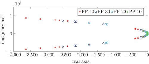
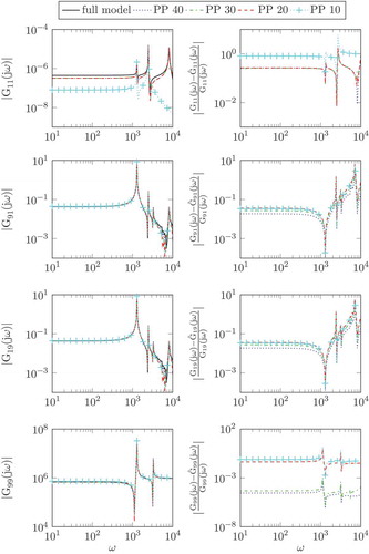
Figure 5. The rows respectively, show the 1st input (mechanical force) to 1st output (displacement), 9th input (electrical potential) to 1st output, 1st input to 9th output (charge) and 9th input to 9th output relations (left) and the respective relative errors (right) of full and reduced systems (dimensions indicated in the legend) for position–position balancing.