Figures & data
Figure 1. (A)The semi-preparative HPLC chromatogram of the n-hexane extract of SL (hSL). The fractions 1 – 9 were collected as shown here. (B) The hSL fractions induced apoptosis in MDA 231 and MCF-7 cells. Cells were treated with different hSL fractions (fractions of hSL: 1-9), which were dissolved in DMSO; the apoptosis assay was performed after 24 h of exposure. The bar graph shows the percentage of apoptotic cells. The base-line apoptosis in the untreated group was normalized with data on the treated group. The data shown are representative of the combined means ± SE from three independent experiments. (C) The LC-MS chromatogram of the fraction hSL-6 (left: HPLC chromatogram, right: negative APCI-MS chromatogram). (D) Fraction 6 of hSL induced apoptosis in MDA 231 and MCF-7 cells. Cells were treated with the different sub-fractions: hSL-6-1 ~ hSL-6-4, which were dissolved in DMSO; the apoptosis assay was performed after 24 h of exposure. The bar graph shows the percentage of apoptotic cells. The base-line apoptosis in the untreated group was normalized with data on the treated group. The data shown are representative of the combined means ± SE from three independent experiments.
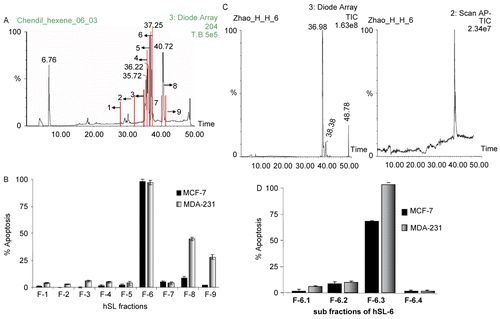
Figure 2. (A)The LC-MS chromatogram of the sub-fraction hSL-6-3 (a, the negative mode TIC (total ion chromatogram) of fraction hSL-6-3; b, the UV-detected HPLC chromatogram of the fraction hSL-6-3; c, the negative mode APCI-MS spectrum corresponding to the major peak in (d), the UV spectrum of the major peak in b.) (B) The chemical structures of the urushiol compounds (1), (2) and (3), isolated from hSL; the major negative ESI-MS/MS fragment ions of these compounds are shown along with the scission site causing the observed fragmentations. Many other (minor) fragmentations were also observed, but not shown here.
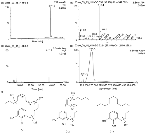
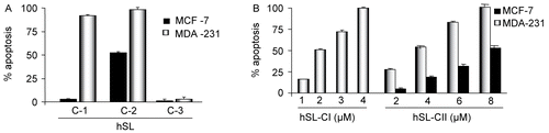
Figure 3. (A) Compounds (1), (2) and (3) of hSL-induced apoptosis in MDA 231 and MCF-7 cells. Cells were treated with the hSL compounds (1), (2) and (3) and apoptosis assays were performed after 24 h of exposure. The bar graph represents the percentage of apoptosis induced by each of these compounds in both the cell lines, and the base-line apoptosis in the untreated group was normalized with the data on the treated group. The data shown are representative of the combined means ± SE from three independent experiments. (B) Compounds (1) and (2) of hSL-induced apoptosis in MDA 231. Cells were treated with the different concentrations of compound (1) (1-4 μM) and (2) (2-8 μM) of hSL and the apoptosis assay was performed after 24h of exposure. Bar graph shows the percentage of apoptotic cells. The base-line apoptosis in the untreated group was normalized with data on the treated group. The data shown are representative of the combined means ± SE from three independent experiments.