1,008
Views
2
CrossRef citations to date
0
Altmetric
Articles

Flow-induced vibration characteristics of pivoted cylinders with splitter-plates

&
Pages 53-63 | Received 30 Jan 2014, Accepted 07 Jul 2014, Published online: 26 Nov 2015

Figures & data

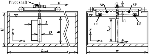
Figure 1. Schematic of experiment apparatus.

Figure 1. Schematic of experiment apparatus.

Table 1. Structural properties of test cylinders with splitter-plates.

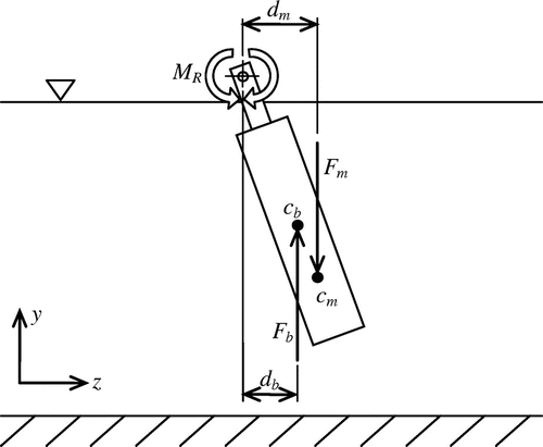
Figure 2. Experiment arrangement of the pivoted circular cylinder.

Figure 2. Experiment arrangement of the pivoted circular cylinder.

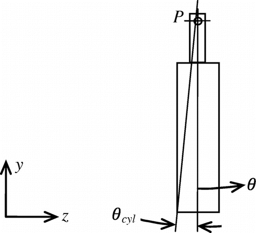
Figure 3. Definition schematic for normalized angular excursion of the pivoted cylinder.

Figure 3. Definition schematic for normalized angular excursion of the pivoted cylinder.

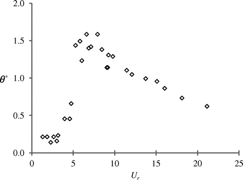
Figure 4. Vibration response of pivoted cylinder without splitter-plate.

Figure 4. Vibration response of pivoted cylinder without splitter-plate.

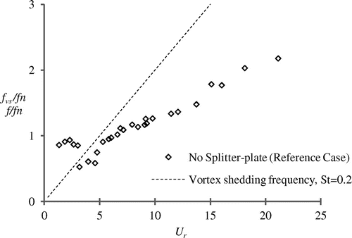
Figure 5. Frequency response of pivoted cylinder without splitter-plate.

Figure 5. Frequency response of pivoted cylinder without splitter-plate.

Figure 6. Vibration responses of pivoted cylinder with splitter-plates l = 0.5D, l = 1.0D, l = 1.5D and l = 2.0D.
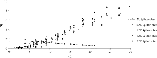
Figure 6. Vibration responses of pivoted cylinder with splitter-plates l = 0.5D, l = 1.0D, l = 1.5D and l = 2.0D.

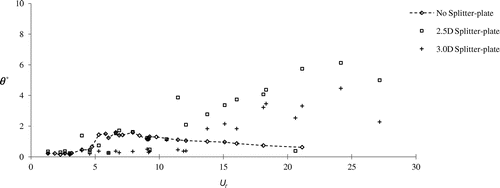
Figure 7. Vibration responses of pivoted cylinder with splitter-plates l = 2.5D and l = 3.0D.

Figure 7. Vibration responses of pivoted cylinder with splitter-plates l = 2.5D and l = 3.0D.

Figure 8. Frequency responses of pivoted cylinder with splitter-plates of various lengths. (Note: f/fn axis truncated at f/fn = 1.5 to aid clarity. Thus, a number of the no splitter-plate data points only are absent).
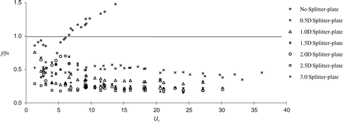
Figure 8. Frequency responses of pivoted cylinder with splitter-plates of various lengths. (Note: f/fn axis truncated at f/fn = 1.5 to aid clarity. Thus, a number of the no splitter-plate data points only are absent).

Figure 9. Average oscillation frequency of each splitter-plate through-out Ur > 10. Note: Upper and lower dashes are offset by 1 standard deviation.
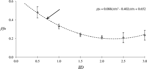
Figure 9. Average oscillation frequency of each splitter-plate through-out Ur > 10. Note: Upper and lower dashes are offset by 1 standard deviation.

Figure 10. Linear trend-line fits to angular excursion of pivoted circular cylinder with attached N-R splitter-plates l = 0.5D, l = 1.0D, l = 1.5D and l = 2.0D.

Figure 10. Linear trend-line fits to angular excursion of pivoted circular cylinder with attached N-R splitter-plates l = 0.5D, l = 1.0D, l = 1.5D and l = 2.0D.

Table 2. Galloping onset-reduced-velocity (Ur-critical) for cylinders with splitter-plates.

Reprints and Corporate Permissions

Please note: Selecting permissions does not provide access to the full text of the article, please see our help page How do I view content?

To request a reprint or corporate permissions for this article, please click on the relevant link below:

Academic Permissions

Please note: Selecting permissions does not provide access to the full text of the article, please see our help page How do I view content?

Obtain permissions instantly via Rightslink by clicking on the button below:

If you are unable to obtain permissions via Rightslink, please complete and submit this Permissions form. For more information, please visit our Permissions help page.