Figures & data
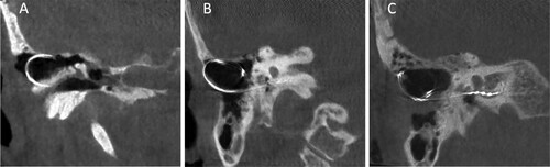
Figure 1 Unaided hearing thresholds tested for patient 1 (A) and patient 2 (B) before cochlear implantation (white circles), after cochlear implantation (black squares), and after revision surgery (white rectangles).
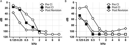
Figure 2 Intraoperative situation of the electrode array of patient 1 at revision surgery. The protruding electrode array is seen through the thinned musculo-periosteal layer (A), liberated from soft tissues (B) and fixed in the mastoid bony bed with a titanium mini-plate.
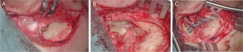
Figure 3 Computed tomography scans of patient 2 at day 2 post initial CI surgery (A), at 10 months post initial CI surgery at onset of symptoms (B) and after revision with fixation of the array and resolution of symptoms (C). The electrode array has worked itself out of the bony mastoid cavity borders (B) and was stably placed back into the cavity with a non-resorbable suture (C).