3,959
Views
17
CrossRef citations to date
0
Altmetric
Original Articles

Abrasive wear evolution in concrete pavements

, , &
Pages 534-548 | Published online: 19 Jun 2012

Figures & data

Figure 1. Description of test equipment.

Figure 1. Description of test equipment.

Figure 2. Forces distribution where F is the weight, μ is the kinetic coefficient of friction between the pavement and wheel, R is the radius of the wheel, W is the angular velocity and V the tangential velocity.
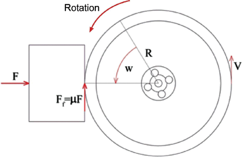
Figure 2. Forces distribution where F is the weight, μ is the kinetic coefficient of friction between the pavement and wheel, R is the radius of the wheel, W is the angular velocity and V the tangential velocity.

Table 1. Combined aggregate distribution.

Figure 3. Workability of the concrete by depth penetration–time curve.

Figure 3. Workability of the concrete by depth penetration–time curve.

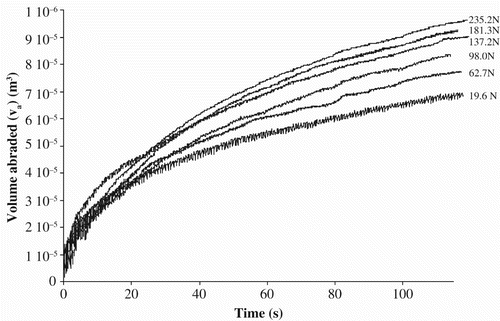
Figure 4. Volume changes for different plummet weights.

Figure 4. Volume changes for different plummet weights.

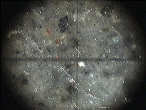
Figure 5. Optical micrograph (200 magnifications) of the studied pavement surface.

Figure 5. Optical micrograph (200 magnifications) of the studied pavement surface.

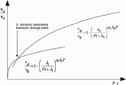
Figure 6. Plot of changes of relative volume with time.

Figure 6. Plot of changes of relative volume with time.

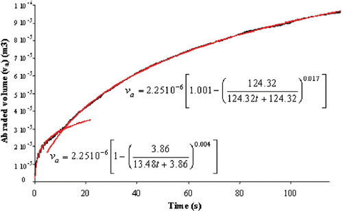
Figure 7. Abraded volume variation of concrete with time for a constant plummet weight of 235 N.

Figure 7. Abraded volume variation of concrete with time for a constant plummet weight of 235 N.

Figure 8. Normal probability plot for the penetration depth at the point between the two curves shown in .
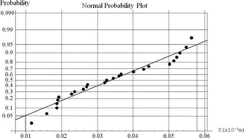
Figure 8. Normal probability plot for the penetration depth at the point between the two curves shown in Figure 4.

Figure 9. Normal probability of the parameters of EquationEquation (18) for the parameter v 0.
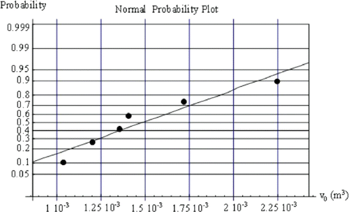
Figure 9. Normal probability of the parameters of EquationEquation (18) for the parameter v 0.

Figure 10. Normal probability of the parameters of EquationEquation (18) for the parameter λ.
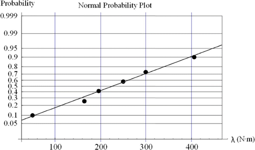
Figure 10. Normal probability of the parameters of EquationEquation (18) for the parameter λ.

Table 2. Regression parameters of the curves shown in .

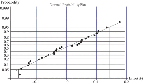
Figure 11. Normal probability plot of errors.

Figure 11. Normal probability plot of errors.

Figure 12. Change of abraded volume with one of the plummet weights studied and its confidence intervals.
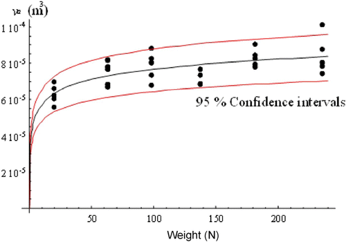
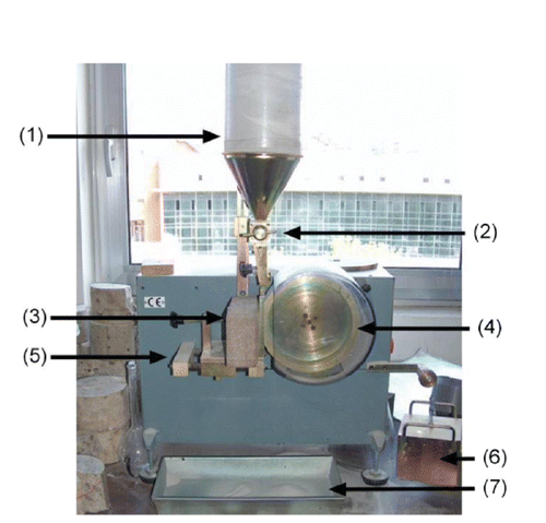
Figure 12. Change of abraded volume with one of the plummet weights studied and its confidence intervals.
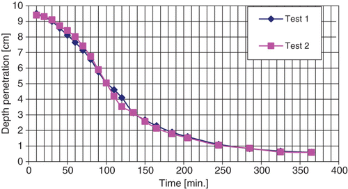
Table 3. Regression parameters for the curves shown in .

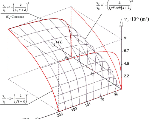
Figure 13. Abrasion surface of concrete. F(N); v a (m3); t (s).

Figure 13. Abrasion surface of concrete. F(N); v a (m3); t (s).

Reprints and Corporate Permissions

Please note: Selecting permissions does not provide access to the full text of the article, please see our help page How do I view content?

To request a reprint or corporate permissions for this article, please click on the relevant link below:

Academic Permissions

Please note: Selecting permissions does not provide access to the full text of the article, please see our help page How do I view content?

Obtain permissions instantly via Rightslink by clicking on the button below:

If you are unable to obtain permissions via Rightslink, please complete and submit this Permissions form. For more information, please visit our Permissions help page.