Figures & data
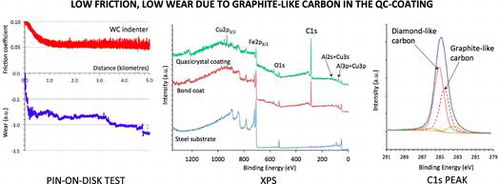
Figure 1. Summary of the state of the art friction against quasicrystals and more conventional hard materials as represented by the friction coefficient recorded as a function of sliding distance during pin-on-disk tests managed under a secondary vacuum of 10−7 mbar [Citation3]. The materials under test are indicated in the figure: hard Cr-steel, sintered alumina and sintered quasicrystalline Al59B3Cu25Fe12.5 (at.%). The indenter was a Cr-steel sphere of 6 mm diameter. Other parameters were: load: 2 N, relative velocity: 5 10−2 m s–1. While Cr-steel sticks on itself, thus producing high friction and emission of abraded particles, it is progressively transferred onto the alumina material. Nothing like this occurs with the quasicrystal, which shows a comparatively moderate friction coefficient against hard steel.
![Figure 1. Summary of the state of the art friction against quasicrystals and more conventional hard materials as represented by the friction coefficient recorded as a function of sliding distance during pin-on-disk tests managed under a secondary vacuum of 10−7 mbar [Citation3]. The materials under test are indicated in the figure: hard Cr-steel, sintered alumina and sintered quasicrystalline Al59B3Cu25Fe12.5 (at.%). The indenter was a Cr-steel sphere of 6 mm diameter. Other parameters were: load: 2 N, relative velocity: 5 10−2 m s–1. While Cr-steel sticks on itself, thus producing high friction and emission of abraded particles, it is progressively transferred onto the alumina material. Nothing like this occurs with the quasicrystal, which shows a comparatively moderate friction coefficient against hard steel.](/cms/asset/fd68560b-5be3-4a28-986a-a82948a75a23/tsta_a_1152563_f0001_oc.gif)
Table 1. Processing parameters of the HVOF projection.
Figure 2. X-ray powder diffraction patterns (λ=KαCu=0.154184 nm) of the steel/Al4Cu9/Al59B3Cu25Fe13 sandwich at room temperature. X-rays investigate only the outmost side of the top layer. The lower pattern is for the sandwich before heat treatment as indicated in the text, and the upper pattern is for the same material but after heat treatment. Before heat-treating, the λ-Al13Fe4 and β-cubic metastable phases are clearly present, as a result of incomplete peritectic growth of the quasicrystal [Citation10]; they have fully disappeared under the effect of the heat treatment. Observe the slight shift of the positions of the quasicrystal peaks due composition change when peritectic growth is completed.
![Figure 2. X-ray powder diffraction patterns (λ=KαCu=0.154184 nm) of the steel/Al4Cu9/Al59B3Cu25Fe13 sandwich at room temperature. X-rays investigate only the outmost side of the top layer. The lower pattern is for the sandwich before heat treatment as indicated in the text, and the upper pattern is for the same material but after heat treatment. Before heat-treating, the λ-Al13Fe4 and β-cubic metastable phases are clearly present, as a result of incomplete peritectic growth of the quasicrystal [Citation10]; they have fully disappeared under the effect of the heat treatment. Observe the slight shift of the positions of the quasicrystal peaks due composition change when peritectic growth is completed.](/cms/asset/d23bf5ba-9634-45d8-94fb-f53825de8dab/tsta_a_1152563_f0002_oc.gif)
Figure 3. Optical micrograph of the steel/BC/i-QC sandwich sliced perpendicular to its plane. The steel substrate is placed on the left side of the figure and the top of the sandwich on the right. An approximate thickness of each layer is indicated.
Figure 4. Graphical presentation of the Berkovich hardness HB (load: 100 mN) as a function of position along a direction perpendicular to the sample plane. Error bars are taken equal to one mean square deviation among five measurements.
Figure 5. Typical scratch test chart recorded for the steel/BC/i-QC sandwich, using a diamond spherical indenter of 0.8 mm diameter. The normal load FN, tangential force FT, their ratio µ=FT/FN, and the simultaneous acoustic emission A.E. are shown.
Figure 6. Pin-on-disk experiments on the steel/BC/i-QC sandwich using a sintered WC-Co indenter (a) and a 100C6 Cr-hard steel (b). The friction coefficient is represented by the upper curves and the change in vertical position of the sample surface-pin ensemble by the lower curve. Observe that both tests lasted for 5000 m.
Figure 7. XPS survey data of the quasicrystalline coating surface before etching (t=0) and following 550 s and 1750 s of etching time with Ar+. Inset: enlargement of the Al2s-Cu3s region corresponding to 550 s (bottom plot) and 1750 s (upper plot) etching with Ar+.
Figure 8. XPS survey data recorded on the transversal cross section of the sandwich, on the steel substrate (spectrum a), the bound coat (spectrum b) and on the quasicrystal layer region (spectrum c).
Figure 9. Peak fitting of the C1s feature (a) before etching and (b) following sputtering with Ar+ for 1750 s.