
Figures & data
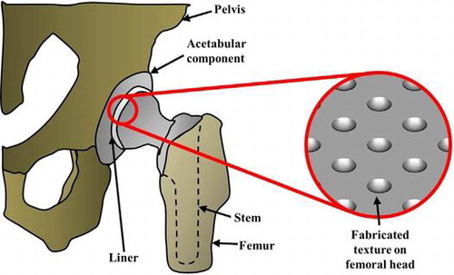
Figure 1. (a) Surface texturing on femoral head [Citation33] and (b) SEM images of different types of fabricated surface texturing.[Citation9]
![Figure 1. (a) Surface texturing on femoral head [Citation33] and (b) SEM images of different types of fabricated surface texturing.[Citation9]](/cms/asset/e95f6e4f-e155-4154-b96b-246e23e41ef7/tsta_a_1240575_f0001_oc.gif)
Table 1 Summary of tribological studies on surface texturing.
Figure 2. Cross section images of deposited (a) a-C:H and (b) Ta-C on stainless steel.[Citation11]
![Figure 2. Cross section images of deposited (a) a-C:H and (b) Ta-C on stainless steel.[Citation11]](/cms/asset/900121a9-bb72-4724-a99a-46f326107d95/tsta_a_1240575_f0002_oc.gif)
Figure 3. Friction coefficient results for different prosthesis heads.[Citation11]
![Figure 3. Friction coefficient results for different prosthesis heads.[Citation11]](/cms/asset/f171580f-8e8f-4168-835a-6663d10d3e7f/tsta_a_1240575_f0003_oc.gif)
Figure 4. SEM images showing (a) as-deposited DLC-coated surface, (b) formation of film transfer due to load, (c) full delamination of coated materials at higher loads, and (d) wear track on dimpled area.[Citation10]
![Figure 4. SEM images showing (a) as-deposited DLC-coated surface, (b) formation of film transfer due to load, (c) full delamination of coated materials at higher loads, and (d) wear track on dimpled area.[Citation10]](/cms/asset/b760d718-95d7-425c-af57-f317c574f705/tsta_a_1240575_f0004_oc.gif)
Figure 5. Schema of a THA with the PMPC-grafted CLPE liner. A transmission electron microscopy image of the surface is shown on the right. Orange and blue lines indicate the PMPC layer and the liner surface, respectively.[Citation68]
![Figure 5. Schema of a THA with the PMPC-grafted CLPE liner. A transmission electron microscopy image of the surface is shown on the right. Orange and blue lines indicate the PMPC layer and the liner surface, respectively.[Citation68]](/cms/asset/ac3bf8d4-4440-46c4-8560-45bc8da5d5a0/tsta_a_1240575_f0005_oc.gif)
Figure 6. Graft conformation at various densities of polymer chains.[Citation12]
![Figure 6. Graft conformation at various densities of polymer chains.[Citation12]](/cms/asset/75d1f9f6-34bc-4ca2-b20c-4f4d79d52b75/tsta_a_1240575_f0006_b.gif)
Table 2 Summary of tribological studies on surface coating.
Table 3 Summary of tribological studies on surface grafting.
Figure 7. Coefficient of dynamic friction of polyelectrolyte-grafted CLPE samples under various lubrication conditions. Data are presented as means ± standard deviations. *Indicates p < 0.05, **indicates p < 0.01, and N.S. indicates no statistical difference.[Citation12]
![Figure 7. Coefficient of dynamic friction of polyelectrolyte-grafted CLPE samples under various lubrication conditions. Data are presented as means ± standard deviations. *Indicates p < 0.05, **indicates p < 0.01, and N.S. indicates no statistical difference.[Citation12]](/cms/asset/3ecb8f5c-94c3-47d0-9e33-cff103e07979/tsta_a_1240575_f0007_b.gif)
Figure 8. Wear mechanism for (a) without dimpled surfaces, (b) smaller depth dimpled surfaces and (c) suitable depth dimpled surfaces.[Citation80]
![Figure 8. Wear mechanism for (a) without dimpled surfaces, (b) smaller depth dimpled surfaces and (c) suitable depth dimpled surfaces.[Citation80]](/cms/asset/473061ee-2245-4b83-af92-eb366f22af39/tsta_a_1240575_f0008_b.gif)
Figure 9. Cross-sectional schematic view of the wear mechanism model for (a) DLC-smooth, (b) DLC with higher density (c) DLC with suitable density (d) DLC with lower density.[Citation43]
![Figure 9. Cross-sectional schematic view of the wear mechanism model for (a) DLC-smooth, (b) DLC with higher density (c) DLC with suitable density (d) DLC with lower density.[Citation43]](/cms/asset/85b5e765-45ea-492e-b258-a927cf61e481/tsta_a_1240575_f0009_oc.gif)