Figures & data
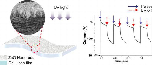
Figure 1. Morphology investigation of the prepared CEZOHN: (a) cross-sectional SEM image and (b) AFM surface image.
Figure 2. TEM images of (a) the CEZOHN with (b) interface morphology and (c) a high resolution image of a ZnO nanorod.
Figure 3. (a) XRD patterns and (b), (c) FTIR absorption spectra of CEZOHN and cellulose film.
Figure 4. (a) PL curves and (b) UV-visible transmittance spectra of cellulose film and CEZOHN.
Figure 5. (a) Schematic of UV photoresponse test setup (b) UV intensity at various distances from the UV source.
Figure 6. Photocurrent outputs at various UV intensities.
Figure 7. Bi-directional photoresponse behavior of the CEZOHN.
Figure 8. UV photocurrent for two different electrodes.
Figure 9. Photoresponse of three UV sensor configurations depicted in the insets.
Figure 10. Photoresponse under sunlight or UV lamp exposure.
Figure 11. (a) Photocurrent under cyclic UV exposure and (b) long-term stability of the UV sensor.
Figure 12. Photoresponse behavior of the UV sensor with (a) flat and (b) 4 cm, (c) 3 cm, (d) 2 cm diameter circular substrates.