Figures & data
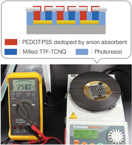
Figure 1. Comparison of TE module structures to absorb heat energy from large area: (a) single-leg TE module structure; (b) π-type TE module structure. Flexible TE sheets necessitate low-κ TE materials like organics and the π-type TE module structure to create ΔT in the sheet thickness.
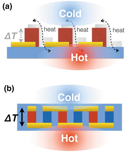
Figure 2. The module pattern of 13 × 13 legs in 40 × 40 mm2 aiming to drive electric devices with a booster circuit: (a) p-type TE leg (red) and n-type TE leg (blue) pattern; (b) bottom electrode pattern; (c) upper electrode pattern. The designed module is expected to drive the booster circuit when the output voltage of single π-unit reaches 3 mV.
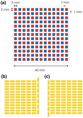
Figure 3. Schematic fabrication process of the organic π-type TE module based on well-established techniques.
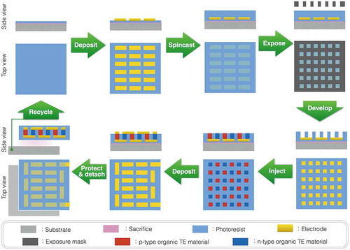
Figure 4. Output voltage of the single π-unit of as-received PEDOT:PSS and the ball-milled TTF-TCNQ mixed with PVC at different ratios.
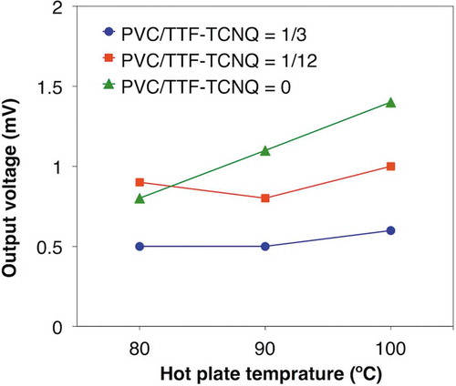
Figure 5. TE performances of PEDOT:PSS dedoped by KW-1000S: (a) Seebeck coefficients; (b) electric conductivities; (c) power factors.
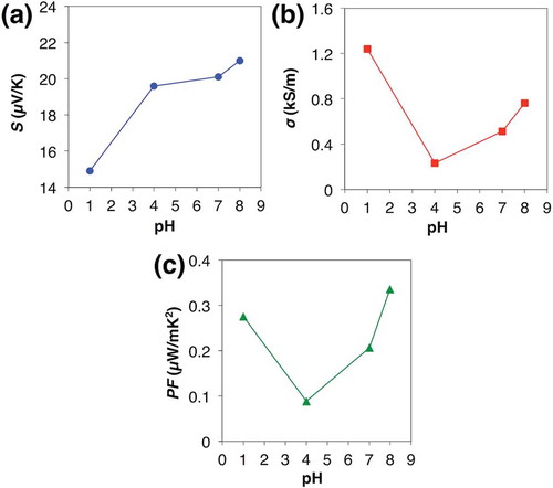
Figure 6. TE performances of the dedoped PEDOT:PSS after the addition of different volume of DMSO per 1 ml PEDOT:PSS solution: (a) Seebeck coefficients; (b) electric conductivities; (c) power factors.

Figure 7. Output voltage of the single π-unit of the ball-milled TTF-TCNQ and as-received PEDOT:PSS or the dedoped PEDOT:PSS after the addition of different volumes of DMSO per 1 ml PEDOT:PSS solution.
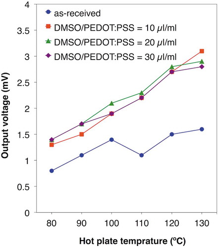
Figure 8. Schematic of the Au penetrated π-type TE module. The Au decreases ΔT of the penetrated n-type leg itself and the next p-type leg due to the heat conduction. Therefore, only the first p-type leg generates electricity.
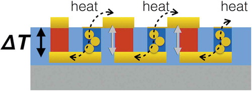
Figure 9. The organic π-type TE modules finalized with ECA: (a) photograph of the module achieving 250 mV; (b) schematic image of the single π-unit measurement and the estimated total resistance based on the measurement assuming the same contact resistance at the upper electrodes and at the bottom electrodes; (c) schematic image of the module measurement and the observed total resistance.
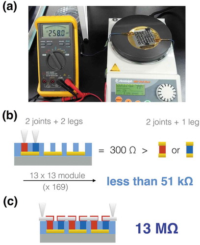
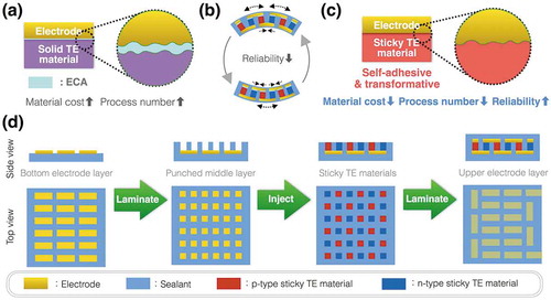
Figure 10. Expected benefits of sticky TE materials: (a) ECAs assist physical contact between solid TE materials and electrodes but form two measurable contact resistances due to low σ of ECAs; (b) Flexible π-type TE modules cause huge mechanical stress on the joints when bent because of the thickness to create ΔT; (c) Sticky TE materials adhere to the electrodes and absorb the mechanical stress; (d) The sticky TE materials enable a simple three-step fabrication process of reliable flexible TE sheets at reasonable material cost.