Figures & data
This paper provides a perspective that theory and experiment are best used in tandem to study DSC devices
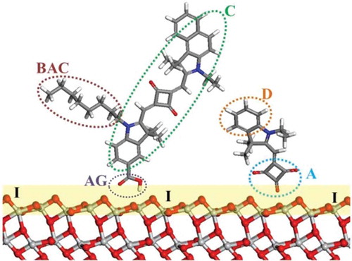
Figure 1. Schematic of DSC device showing key steps for device operation (in black) and competing processes (in red).
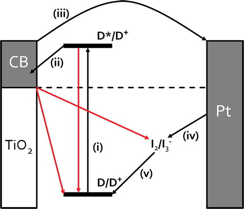
Figure 2. Schematic of DSC components illustrating dye co-sensitization: C, dye chromophore; BAC, bulky alkyl chain; D, donor; A, acceptor; AG, anchoring group; I, TiO2/dye interface. Red, O; light grey, Ti; blue, N; grey, C; white, H.
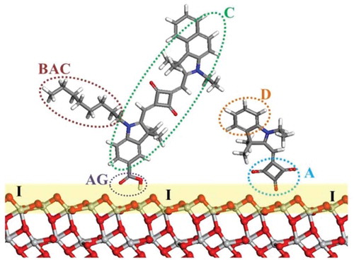
Figure 3. Possible binding modes for a carboxylate anchor group binding to a metal oxide surface. Reproduced with permission from [Citation85].
![Figure 3. Possible binding modes for a carboxylate anchor group binding to a metal oxide surface. Reproduced with permission from [Citation85].](/cms/asset/81eb8866-e16c-470a-a7d3-bc36a4d27d9d/tsta_a_1492858_f0003_b.gif)
Table 1. DSC device parameters for triphenylamine dyes with 1,2 or 3 linkers. Errors in brackets. Reproduced with permission from [Citation57].
Figure 4. Dye anchoring points A, B, C and D on a half-squaraine chromophore. Reproduced with permission from [Citation7].
![Figure 4. Dye anchoring points A, B, C and D on a half-squaraine chromophore. Reproduced with permission from [Citation7].](/cms/asset/473021ba-18e9-4654-a532-69eafa3c7b84/tsta_a_1492858_f0004_c.jpg)
Figure 5. Molecular structures of (a) N3, (b) HSQ1 and (c) SQ1. Reproduced with permission from [Citation68].
![Figure 5. Molecular structures of (a) N3, (b) HSQ1 and (c) SQ1. Reproduced with permission from [Citation68].](/cms/asset/ec0c6a12-ba49-4b6a-8ef0-4233f2cb5cee/tsta_a_1492858_f0005_b.gif)
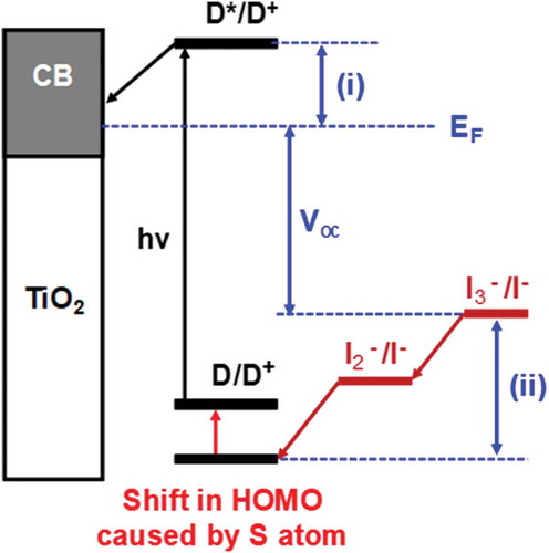
Figure 6. Shift in HOMO caused by the addition of sulphur atom to half-squaraine sensitizer. EF = Fermi level, (i) dye injection overpotential and (ii) dye regeneration overpotential. D = ground state dye, D* = excited state dye, D+; = oxidized dye, CB =conduction band, hν = sunlight and Voc = open circuit voltage.