Figures & data
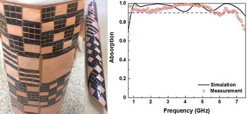
Figure 1. Design of the unit cell for ultrathin MMA. Three-dimensional periodic structure of the unit cell (a) without and (b) with conductive fibers.
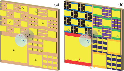
Figure 2. Difference between MMA without and with conductive fibers. (a) Effective impedance and (b) simulated absorption spectrum of the proposed MMA without and with conductive fibers.
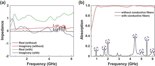
Figure 3. Physical mechanism of the broadband absorption. Simulated the induced surface currents in the metallic pattern (first column), the continuous metallic plane (second column) and three-dimensional distributions for the power loss (third column) at 0.95, 1.70, 2.00 and 4.40 GHz.
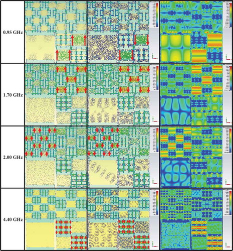
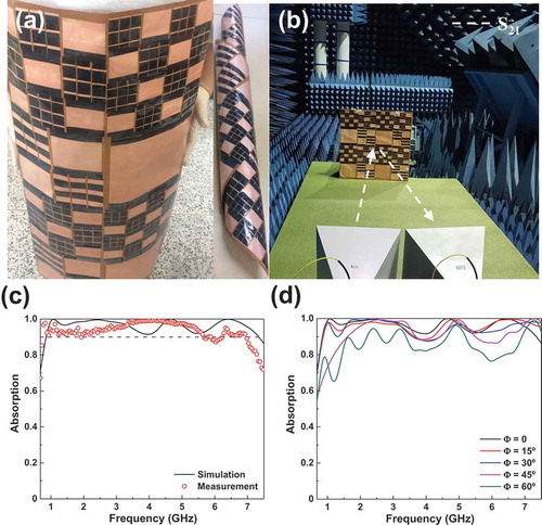
Figure 4. Experiment and performance of the MMA. Photos of (a) the fabricated sample with conductive fibers and (b) the measurement set-up. (c) Simulated and measured absorption spectra for the proposed structure.
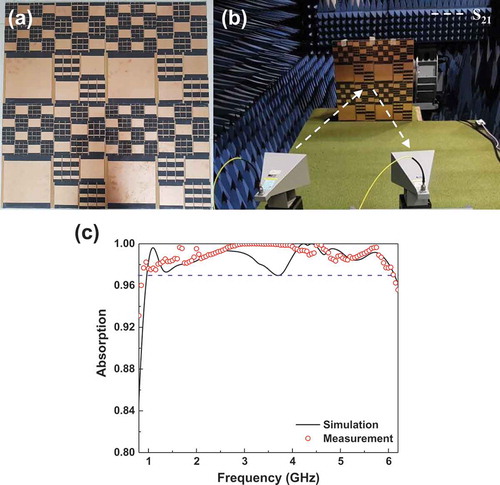
Figure 5. Application of the MMA model for flexibility. Photographs of (a) the fabricated flexible sample with conductive fibers and (b) the measurement configuration. (c) Simulated and experimental absorption spectra of the suggested flexible MMA. (d) Simulated absorption spectra according to the incident angle for the TE polarization.