
Figures & data
Figure 1. Developments in hybrid energy systems based on nanogenerators and energy storage devices through integration, hybridization, and all-in-one design for self-charging capability of future electronics. Reprinted, with permission, from [Citation14]. © 2017, Kim et al
![Figure 1. Developments in hybrid energy systems based on nanogenerators and energy storage devices through integration, hybridization, and all-in-one design for self-charging capability of future electronics. Reprinted, with permission, from [Citation14]. © 2017, Kim et al](/cms/asset/37f31d1c-9c18-4ff8-a28b-e9a8d759a7aa/tsta_a_1962203_f0001_oc.jpg)
Figure 2. Ragone plot for the fundamental electrical energy storage devices
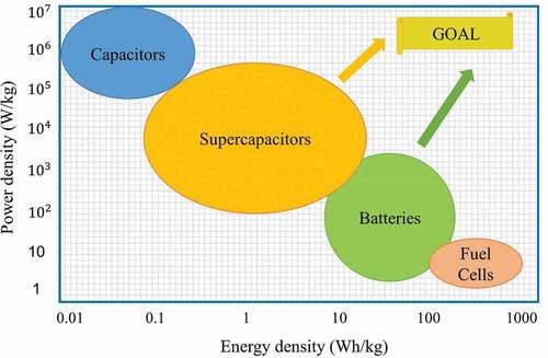
Figure 3. The potential applications of textile-based electrochemical energy storage devices in various areas. Reprinted, with permission, from [Citation38]. © 2016, Wiley-VCH
![Figure 3. The potential applications of textile-based electrochemical energy storage devices in various areas. Reprinted, with permission, from [Citation38]. © 2016, Wiley-VCH](/cms/asset/0c3be5ee-c003-4784-8071-4cee3dc3cb6e/tsta_a_1962203_f0003_oc.jpg)
Figure 4. Schematic representation of a printed battery in a sandwich cell architecture, where the anode and cathode of the battery are stacked together. Reprinted, with permission, from [Citation48]. © 2018, John Wiley & Sons
![Figure 4. Schematic representation of a printed battery in a sandwich cell architecture, where the anode and cathode of the battery are stacked together. Reprinted, with permission, from [Citation48]. © 2018, John Wiley & Sons](/cms/asset/6f01c09e-4f41-4135-b5bc-7aa77c772aa9/tsta_a_1962203_f0004_oc.jpg)
Figure 5. Classification of printing technologies
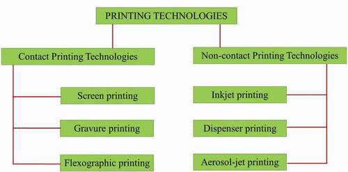
Figure 6. A). Stepwise screen printing of a Zn-Ag2O battery on a stretchable textile using a styrene-isoprene-styrene (SIS) binder. B). The discharge capacity during prolonged cycle, cycled with 3 mA h cm−2. (A, B) Reprinted, with permission, from [Citation82]. © 2016, Wiley-VCH
![Figure 6. A). Stepwise screen printing of a Zn-Ag2O battery on a stretchable textile using a styrene-isoprene-styrene (SIS) binder. B). The discharge capacity during prolonged cycle, cycled with 3 mA h cm−2. (A, B) Reprinted, with permission, from [Citation82]. © 2016, Wiley-VCH](/cms/asset/f69be053-4ae8-455a-bae9-5cbcc12090bd/tsta_a_1962203_f0006_oc.jpg)
Table 1. Printing technologies applied to e-textiles: resolution and advantages and disadvantages
Figure 7. Classification of power supply mechanisms for electronic textiles and wearables
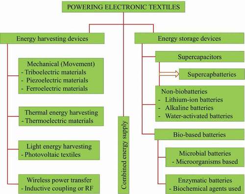
Figure 8. A). Self-powered textile device produced by hybridizing fiber-shaped triboelectric nanogenerators (F-TENG), dye-sensitized solar cells (F-DSSC), and supercapacitors (F-SC). B). Circuit diagram of the self-charging powered textile for wearable electronics. C). Charging curve of the F-DSSC and the F-TENG, where the light blue-shaded area corresponds to the charging curve of the F-DSSC and the light red–shaded area corresponds to the charging curve of the F–DSSC/F-TENG hybrid. The top left corner inset shows an enlarged curve during the F-DSSC charging period, and the bottom right corner inset shows the rectified short-circuit current, ISC of F-TENGs. (A, B, C) Reprinted, with permission, from [Citation103]. © 2016, The Authors, some rights reserved; exclusive licensee AAAS. Distributed under a CC BY-NC 4.0 license
![Figure 8. A). Self-powered textile device produced by hybridizing fiber-shaped triboelectric nanogenerators (F-TENG), dye-sensitized solar cells (F-DSSC), and supercapacitors (F-SC). B). Circuit diagram of the self-charging powered textile for wearable electronics. C). Charging curve of the F-DSSC and the F-TENG, where the light blue-shaded area corresponds to the charging curve of the F-DSSC and the light red–shaded area corresponds to the charging curve of the F–DSSC/F-TENG hybrid. The top left corner inset shows an enlarged curve during the F-DSSC charging period, and the bottom right corner inset shows the rectified short-circuit current, ISC of F-TENGs. (A, B, C) Reprinted, with permission, from [Citation103]. © 2016, The Authors, some rights reserved; exclusive licensee AAAS. Distributed under a CC BY-NC 4.0 license](/cms/asset/4359fb2a-831a-4b28-a098-9fcc11975ba8/tsta_a_1962203_f0008_oc.jpg)
Figure 9. Schematic of different energy hybridization approaches between battery and supercapacitor electrodes and materials
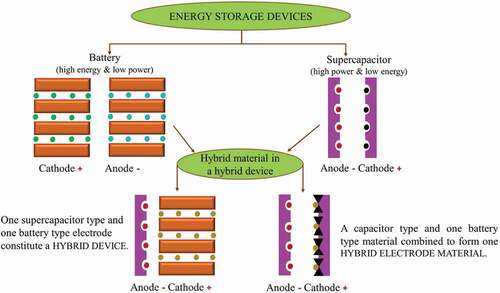
Figure 10. A). Schematic representation of textile-based battery including each functional layers and textile packaging. B). Two screen-printed textile-based liquid-activated batteries before activation. C). after activation by using 20 μL of deionized (D.I.) water and connected in series to power a 1.6 V light-emitting diode. (A, B, C) Reprinted, with permission, from [Citation118]. © 2015, IOP Publishing. Distributed under a CC BY 3.0 license
![Figure 10. A). Schematic representation of textile-based battery including each functional layers and textile packaging. B). Two screen-printed textile-based liquid-activated batteries before activation. C). after activation by using 20 μL of deionized (D.I.) water and connected in series to power a 1.6 V light-emitting diode. (A, B, C) Reprinted, with permission, from [Citation118]. © 2015, IOP Publishing. Distributed under a CC BY 3.0 license](/cms/asset/659d360f-5b82-4502-8776-c1349a5b3830/tsta_a_1962203_f0010_oc.jpg)
Figure 11. Characterization of the flexible Zn-MnO2 based alkaline printed battery. A). Demonstration of two flexible batteries connected in series to power a green light-emitting diode. B). The flexible batteries connected in series were able to power a green light-emitting diode when flexed to a bend radius of 0.3 cm. C). Discharge profile of the flexible battery when discharged at 0.5, 1, and 2 mA when flat. D). Discharge profile of the flexible battery when flexed to different radii of curvature while discharging at 1 mA. (A, B, C, D) Reprinted, with permission, from [Citation122]. © 2011, Wiley-VCH
![Figure 11. Characterization of the flexible Zn-MnO2 based alkaline printed battery. A). Demonstration of two flexible batteries connected in series to power a green light-emitting diode. B). The flexible batteries connected in series were able to power a green light-emitting diode when flexed to a bend radius of 0.3 cm. C). Discharge profile of the flexible battery when discharged at 0.5, 1, and 2 mA when flat. D). Discharge profile of the flexible battery when flexed to different radii of curvature while discharging at 1 mA. (A, B, C, D) Reprinted, with permission, from [Citation122]. © 2011, Wiley-VCH](/cms/asset/ec3ca786-6ec2-4b67-8125-d6b397cd88af/tsta_a_1962203_f0011_oc.jpg)
Figure 12. A). Two screen printed monovalent silver oxide -zinc (Ag2O-Zn) alkaline battery cells on two separate fabrics and combined in series using flexible Cu/Ni electrical threads for maximum electrical contact. B) Power discharge curve showing the power generated as a function of time for different battery cells connected in series at a discharge current of 100 µA. (A, B) Reprinted, with permission, from [Citation132]. © 2018, IEEE
![Figure 12. A). Two screen printed monovalent silver oxide -zinc (Ag2O-Zn) alkaline battery cells on two separate fabrics and combined in series using flexible Cu/Ni electrical threads for maximum electrical contact. B) Power discharge curve showing the power generated as a function of time for different battery cells connected in series at a discharge current of 100 µA. (A, B) Reprinted, with permission, from [Citation132]. © 2018, IEEE](/cms/asset/15c75995-2783-421b-9391-0448dea1d87b/tsta_a_1962203_f0012_oc.jpg)
Table 2. Summary of merits and demerits for different batteries in terms of safety, capacity, and cycle life