135
Views
4
CrossRef citations to date
0
Altmetric
Original Articles

Short-range-order stacking in superconducting composite crystal: simulation of diffuse scattering in neutron powder diffraction pattern of deuterated sodium cobaltate

, , , &
Pages 2773-2779 | Received 30 Aug 2006, Accepted 19 Oct 2006, Published online: 03 Dec 2010

Figures & data

Figure 1. Possible configurations of fundamental structure model of the guest sheet, based on a cell a2 = b2 = 3.26 Å, c = 9.8 Å. The cell is based on the axes a2 = (2/3)a1 + (4/3)b1, b2 = −(4/3)a1–(2/3)b1 and c = c2H/2 = c3R/3, whereas the basic axes a1 and b1 are used for the CoO2 host layer. Assumed local symmetry operations in a layer unit are threefold rotation axis and inversion centre. Layer unit is illustrated using circles with dark rims for a half part (0.0 ≤ z < 0.5) and with light rims for the other half part (−0.5 ≤ z < 0.0). Occupancies of Na, O and D are estimated as 0.47, 0.89 and 0.61, respectively. Four configurations, Q1, Q2, Q3 and Q4, with respective shift vectors 0, (1/2)a2, (1/2)b2 and (1/2)a2 + (1/2)b2, are considered.
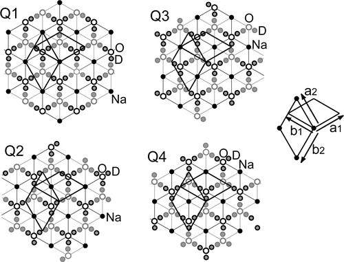
Figure 1. Possible configurations of fundamental structure model of the guest sheet, based on a cell a2 = b2 = 3.26 Å, c = 9.8 Å. The cell is based on the axes a2 = (2/3)a1 + (4/3)b1, b2 = −(4/3)a1–(2/3)b1 and c = c2H/2 = c3R/3, whereas the basic axes a1 and b1 are used for the CoO2 host layer. Assumed local symmetry operations in a layer unit are threefold rotation axis and inversion centre. Layer unit is illustrated using circles with dark rims for a half part (0.0 ≤ z < 0.5) and with light rims for the other half part (−0.5 ≤ z < 0.0). Occupancies of Na, O and D are estimated as 0.47, 0.89 and 0.61, respectively. Four configurations, Q1, Q2, Q3 and Q4, with respective shift vectors 0, (1/2)a2, (1/2)b2 and (1/2)a2 + (1/2)b2, are considered.

Table 1. Probability table (P) for an interlayer short-range order model.

Figure 2. (a) The powder neutron diffraction pattern simulated using the layer units shown in and the probability table shown in and (b) the observed pattern of 3R and 2H phases.
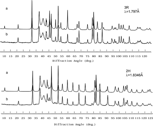
Figure 2. (a) The powder neutron diffraction pattern simulated using the layer units shown in figure 1 and the probability table shown in table 1 and (b) the observed pattern of 3R and 2H phases.

Figure 3. A probable model of intralayer ordering in the guest part. Bounded projections along [00] (left) and along [110] (right). Occupancies of Na sites are assumed to be 1.0 (small solid circle) and 0.2 (hatched circle), and those of O and D are estimated as 0.89 and 0.96.

Figure 3. A probable model of intralayer ordering in the guest part. Bounded projections along [00] (left) and along [110] (right). Occupancies of Na sites are assumed to be 1.0 (small solid circle) and 0.2 (hatched circle), and those of O and D are estimated as 0.89 and 0.96.

Figure 4. (a) The simulated powder neutron diffraction pattern of 3R phase based on a commensurate composite crystal model (see text) and (b) the observed pattern.

Figure 4. (a) The simulated powder neutron diffraction pattern of 3R phase based on a commensurate composite crystal model (see text) and (b) the observed pattern.