
Figures & data
Table 1. Crystallography of possible deformation twinning modes in CP titanium using standard nomenclature for the twin plane K1, shear direction η1, second undistorted plane K2 and direction η2 lying in K2 and the plane of shear [5–7]. For each deformation twinning mode a specific K1 is selected to emphasize the crystallographic relations between K1, η1, K2 and η2. q is the complexity of the shuffles required to ensure all atoms in the twin are carried into their final correct positions [5–7]. ‘T’ and ‘C’ refer to the nomenclature of tension (T) and compression twins (C), which define whether the shape change produced by the twinning mode causes extension or contraction along the c-axis, respectively [Citation5,6].
Figure 1. (colour online) Geometry of (a) and (b)
twinning in a single crystal of titanium viewed normal to
. The composition plane K1, twinning direction η1, conjugate twinning direction η2 and shear magnitude S are labelled. The shaded regions represent the super cell that undergoes the shear. The lattice point labelling system is that specified by Crocker and Bevis [Citation26]. Using the ABAB stacking sequence designation of the h.c.p. crystal structure of α-titanium, the atom positions are represented by circles and squares for the A layer and triangles for the B layer. The atom positions displayed represent the projection of four
planes: circles lie on the plane of the page, squares are one
d-spacing below the page, upright triangles two
d-spacings below the page and inverted triangles three
d-spacings below the page. Representations of the macroscopic shape change to a single crystal of titanium deformed by twinning on
and
are shown in (c) and (d), respectively. It is evident that these twinning modes facilitate a macroscopic compression in line with the c-axis as in both cases; the pre-twinning crystal length l0 is greater in magnitude than the post-twinning crystal length l1.
![Figure 1. (colour online) Geometry of (a) and (b) twinning in a single crystal of titanium viewed normal to . The composition plane K1, twinning direction η1, conjugate twinning direction η2 and shear magnitude S are labelled. The shaded regions represent the super cell that undergoes the shear. The lattice point labelling system is that specified by Crocker and Bevis [Citation26]. Using the ABAB stacking sequence designation of the h.c.p. crystal structure of α-titanium, the atom positions are represented by circles and squares for the A layer and triangles for the B layer. The atom positions displayed represent the projection of four planes: circles lie on the plane of the page, squares are one d-spacing below the page, upright triangles two d-spacings below the page and inverted triangles three d-spacings below the page. Representations of the macroscopic shape change to a single crystal of titanium deformed by twinning on and are shown in (c) and (d), respectively. It is evident that these twinning modes facilitate a macroscopic compression in line with the c-axis as in both cases; the pre-twinning crystal length l0 is greater in magnitude than the post-twinning crystal length l1.](/cms/asset/aadd2c38-b85d-4f4b-9d7b-7588e993a441/tphm_a_1051157_f0001_oc.gif)
Table 2. CP titanium impurity levels for C, H, N and O determined from combustion analysis and for Fe determined from inductively coupled plasma optical emission spectrometry.
Figure 2. (colour online) (a) EBSD scan of an individual deformation twin and smaller
twins acquired at 25 kV with a 0.5 μm step size, inverse pole figure colouring and band contrast, with the
twin outlined in white and the smaller
twins outlined in black. The loading direction is in the horizontal direction. (b) Bright field image of the TEM specimen taken from the boxed region in (a). (c) Electron diffraction pattern from (b) viewed down the
zone (
in the three index notation) common to both the matrix and the twin confirming twinning on
. This electron diffraction pattern has been image processed to highlight the
and
twin spots, which have a low intensity because of their large
.
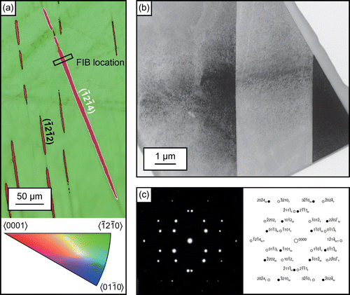
Figure 3. Electron diffraction patterns from Figure (b), (a) viewed down the zone ([2 1 0] in the three index notation) (b) viewed down the
zone (
in the three index notation) and (c) viewed down the
zone (
in the three index notation) common to both the matrix and the twin confirming twinning on
. As in Figure , the electron diffraction patterns have been image processed to highlight the
and
twin spots, which have a low intensity because of their large
.
![Figure 3. Electron diffraction patterns from Figure 2(b), (a) viewed down the zone ([2 1 0] in the three index notation) (b) viewed down the zone ( in the three index notation) and (c) viewed down the zone ( in the three index notation) common to both the matrix and the twin confirming twinning on . As in Figure 2, the electron diffraction patterns have been image processed to highlight the and twin spots, which have a low intensity because of their large .](/cms/asset/3b837e34-7708-4904-b660-efdfb93ed818/tphm_a_1051157_f0003_b.gif)
Figure 4. (colour online) (a) EBSD scan of a longitudinally sectioned ballistically tested projectile acquired at 25 kV with a 15 μm step size, inverse pole figure colouring and band contrast. The loading direction is in the horizontal direction, with the impact face on the right-hand side. (b) Band contrast with grains whose c-axes were within 6° of the loading direction highlighted in green. (c)–(e) EBSD scans of the highlighted green grains in (b) acquired at 25 kV with a 0.5 μm step size, with inverse pole figure colouring and band contrast, showing large twins outlined in white and smaller
twins outlined in black.
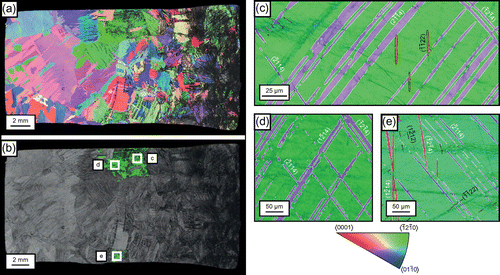
Table 3. Area fractions of deformation twins in Figures (a) and (c)–(e) as percentages of the EBSD scan area of a grain, and area percentage of twinned area for  and deformation twins.
Table 4. Highest Schmid factors for twinning within each possible deformation twinning mode for the grains shown in Figures (a) and (c)–(e), assuming plane strain compression loading in the x-direction which is horizontal across the page in each of these figures, compressing the crystal c-axis.
Table 5. Schmid factors for the six and deformation twin variants for the grains shown in Figures (a) and (c)–(e), assuming plane strain compression loading in the x-direction which is horizontal across the page in each of these figures, compressing the crystal c-axis.
Figure 5. (colour online) (a) and (b) The variation of positive Schmid factors for loading in compression for twinning on ; the position where the Schmid factor is at a maximum of 0.5 is 6.5° away from [0 0 0 1] and 45° from the
pole. (c) and (d) Maximum positive Schmid factors for loading in compression for twinning on
. In (a)–(d) the [0 0 0 1] pole is indicated by a black dot.
![Figure 5. (colour online) (a) and (b) The variation of positive Schmid factors for loading in compression for twinning on ; the position where the Schmid factor is at a maximum of 0.5 is 6.5° away from [0 0 0 1] and 45° from the pole. (c) and (d) Maximum positive Schmid factors for loading in compression for twinning on . In (a)–(d) the [0 0 0 1] pole is indicated by a black dot.](/cms/asset/67e79a9c-9f4a-424f-b914-7b485f23f920/tphm_a_1051157_f0005_oc.gif)