
Figures & data
Table 1. Experimental conditions for deformation of the two olivine single crystals.
Figure 1. Typical PoEM8-PoEM9 microstructures: (a) WBDF micrograph obtained with the diffraction vector (
and
dislocations are in contrast); (b) WBDF micrograph obtained with
g
=
on the same region as (a) (only
dislocations are in contrast); (c) Corresponding 3D reconstruction (
,
and
dislocations are shown in blue, orange and yellow colours, respectively), the two yellow arrows point out
junctions; (d) Characteristic microstructure of PoEM9 only composed of
dislocations, with a large majority of straight lined screw segments, few non-screw segments and scarce dislocation loops [Citation10]; (e) 3D reconstruction of (d) (
dislocations are shown in orange).
![Figure 1. Typical PoEM8-PoEM9 microstructures: (a) WBDF micrograph obtained with the diffraction vector ( and dislocations are in contrast); (b) WBDF micrograph obtained with g = on the same region as (a) (only dislocations are in contrast); (c) Corresponding 3D reconstruction (, and dislocations are shown in blue, orange and yellow colours, respectively), the two yellow arrows point out junctions; (d) Characteristic microstructure of PoEM9 only composed of dislocations, with a large majority of straight lined screw segments, few non-screw segments and scarce dislocation loops [Citation10]; (e) 3D reconstruction of (d) ( dislocations are shown in orange).](/cms/asset/66891635-7644-4334-a0b7-b8f11947eeaf/tphm_a_1367858_f0001_oc.gif)
Figure 2. Main slip systems and cross-slip or/and collinear annihilations in PoEM8: (a) WBDF micrograph performed with
g
= , with a tilt angle of 56° where: the
and the
plane are indicated, black arrows point out probable specific configurations, which may be cross-slip or/and collinear interactions with small dislocation loops (some isolated loop, with approximately the same sizes, are in the vicinity); (b) Three Enlargement of (a), upper part; (c) Enlargement of (a), upper part of the image centre; (d) Enlargement of (a), lower part of the image centre; (e) Enlargement of (a), lower part; (f) Corresponding reconstruction volume, with a projected angle of 63° where: black dislocation segments designate the edge-on
slip systems, white dislocation segments designate the edge-on
slip systems, the yellow arrow points out a
junction.
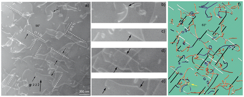
Figure 3. Dislocation climb planes (the dislocation segments which lie on the planes are coloured in red and the dislocation segments are coloured in green for the
planes): (a) 3D reconstruction of a PoEM8 tilted series obtained with
g
=
, with a projected angle of 63° (the
and
planes are edge-on with this projection condition); (b) Projection angle of 76° (the
and
planes are edge-on along this direction); (c) 282° tilt angle (the
,
,
and
planes are edge-on with this orientation); (d) Projection angle of 320° (the
and
planes are edge-on with this projection condition), the white dashed square points out a break-up of a dislocation dipole by climb, the four yellow arrows point out
junctions; The numerous dislocation segments which lie on the
and the
planes (19 segments in
and 23 segments in
) show the occurrence of climb in PoEM8.
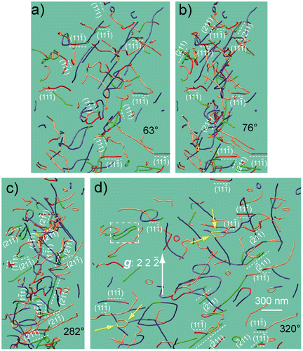
Figure 4. Double cross-slip mechanism: (a) Reconstructed volume of a dislocation obtained with
g
=
(projected angle of −143°, −117°, −53°, −27°, 37°, 63°, 127° and 153°), the
planes are edge-on for the −117° and 63° tilt angles (
zone axis) and the
planes are edge-on for the −53° and 127° tilt angles (
zone axis); (b) Reconstructed volume of a
dislocation performed with the same diffraction vector as (a) (projected angle of −117°, −41°, −12°, 63°, 116° and 168°), the
planes are edge-on for the −117° and 63° tilt angles and the
planes are edge-on for the −12° and 168° tilt angles (
zone axis); (c) Complex dislocation configuration composed of a
and a
dislocation, a
junction (yellow segment) and an attractive
/
dislocation crossed state; moreover a double cross-slip configuration of the
dislocation is revealed (same description as (a)); (d) Simulation of the Kikuchi lines, between −165° and 180°, in kinematic conditions (Electron Diffraction Software [Citation33]); the
and
Kikuchi lines are shown in blue colour (in reference with the
dislocation in blue colour) and the
and
Kikuchi lines are shown in red colour (in reference with the
dislocation in orange colour); (e) Summary of the three dislocation configurations in (a), (b) and (c) for tilt angles of 0°, 63° and −27°, respectively (the white dislocations segments designate the
slip systems, the light grey dislocations segments refer to the
slip systems and the black dislocation segments designate the
slip systems), the yellow arrow points out a
junction.
![Figure 4. Double cross-slip mechanism: (a) Reconstructed volume of a dislocation obtained with g = (projected angle of −143°, −117°, −53°, −27°, 37°, 63°, 127° and 153°), the planes are edge-on for the −117° and 63° tilt angles ( zone axis) and the planes are edge-on for the −53° and 127° tilt angles ( zone axis); (b) Reconstructed volume of a dislocation performed with the same diffraction vector as (a) (projected angle of −117°, −41°, −12°, 63°, 116° and 168°), the planes are edge-on for the −117° and 63° tilt angles and the planes are edge-on for the −12° and 168° tilt angles ( zone axis); (c) Complex dislocation configuration composed of a and a dislocation, a junction (yellow segment) and an attractive / dislocation crossed state; moreover a double cross-slip configuration of the dislocation is revealed (same description as (a)); (d) Simulation of the Kikuchi lines, between −165° and 180°, in kinematic conditions (Electron Diffraction Software [Citation33]); the and Kikuchi lines are shown in blue colour (in reference with the dislocation in blue colour) and the and Kikuchi lines are shown in red colour (in reference with the dislocation in orange colour); (e) Summary of the three dislocation configurations in (a), (b) and (c) for tilt angles of 0°, 63° and −27°, respectively (the white dislocations segments designate the slip systems, the light grey dislocations segments refer to the slip systems and the black dislocation segments designate the slip systems), the yellow arrow points out a junction.](/cms/asset/a4cb1a83-81a2-4dbd-90f6-765cb3d6922d/tphm_a_1367858_f0004_oc.gif)