Figures & data
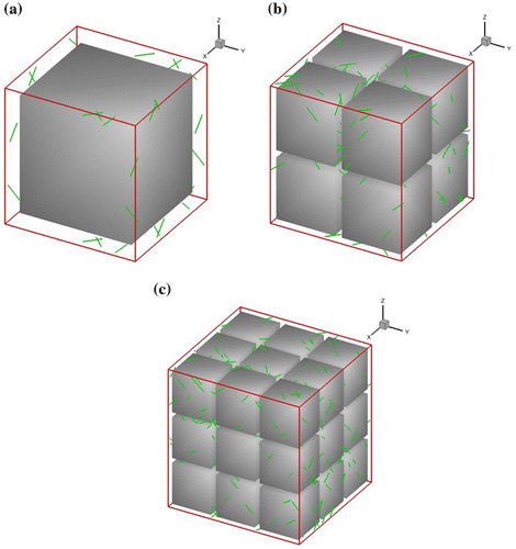
Figure 1. (colour online) RVEs with (a) 1, (b) 8 and (c) 27 precipitates, where initial Frank-Read dislocation sources are randomly distributed in the -phase matrix.

Figure 2. (colour online) Stress–strain response for RVEs with different number of precipitates for (a) [0 0 1] orientation; (b) [1 1 1] orientation.
![Figure 2. (colour online) Stress–strain response for RVEs with different number of precipitates for (a) [0 0 1] orientation; (b) [1 1 1] orientation.](/cms/asset/582ff001-9a57-4bd0-8ed8-06827a53d3be/tphm_a_1447159_f0002_oc.gif)
Figure 3. (colour online) Dislocation density against time for RVEs with different number of precipitates for (a) [0 0 1] orientation; (b) [1 1 1] orientation.
![Figure 3. (colour online) Dislocation density against time for RVEs with different number of precipitates for (a) [0 0 1] orientation; (b) [1 1 1] orientation.](/cms/asset/23aa165c-2a65-4e19-bfc4-48d80b639048/tphm_a_1447159_f0003_oc.gif)
Table 1. The parameters used in 3D DDD simulations.
Figure 4. (colour online) Cyclic stress–strain response simulated with 3D DDD model at for (a) [0 0 1] and (b) [1 1 1] orientations.
![Figure 4. (colour online) Cyclic stress–strain response simulated with 3D DDD model at for (a) [0 0 1] and (b) [1 1 1] orientations.](/cms/asset/d171a481-78db-4bc3-b644-a50caaf4b908/tphm_a_1447159_f0004_oc.gif)
Figure 5. (colour online) Dislocation networks for [0 0 1] orientation at (a) time = 1 s, (b) time = 4 s, (c) time = 5 s, (d) time = 8 s and (e) time = 9 s.
![Figure 5. (colour online) Dislocation networks for [0 0 1] orientation at (a) time = 1 s, (b) time = 4 s, (c) time = 5 s, (d) time = 8 s and (e) time = 9 s.](/cms/asset/d343c3d2-f348-46cd-a99a-77e7d836b0f2/tphm_a_1447159_f0005_oc.gif)
Figure 6. (colour online) Dislocation networks for [1 1 1] orientation at (a) time = 1 s, (b) time = 4 s, (c) time = 5 s, (d) time = 8 s and (e) time = 9 s.
![Figure 6. (colour online) Dislocation networks for [1 1 1] orientation at (a) time = 1 s, (b) time = 4 s, (c) time = 5 s, (d) time = 8 s and (e) time = 9 s.](/cms/asset/990c188b-1ab0-4a19-8c0e-9724ebc92c46/tphm_a_1447159_f0006_oc.gif)
Figure 7. (colour online) Maximum-shear plastic strain contour at strain = 1% for (a) [0 0 1] and (b) [1 1 1] orientations.
![Figure 7. (colour online) Maximum-shear plastic strain contour at strain = 1% for (a) [0 0 1] and (b) [1 1 1] orientations.](/cms/asset/f5c152f3-c424-4124-abf5-b9ffac56afdc/tphm_a_1447159_f0007_oc.gif)
Figure 8. (colour online) Stress–strain response with and without precipitate for (a) [0 0 1] and (b) [1 1 1] orientations.
![Figure 8. (colour online) Stress–strain response with and without precipitate for (a) [0 0 1] and (b) [1 1 1] orientations.](/cms/asset/ba4a1408-cd16-41a1-b0eb-08d3c3a79be2/tphm_a_1447159_f0008_oc.gif)
Figure 9. (colour online) Stress–strain response with and without shearing of precipitate by dislocations for (a) [0 0 1] and (b) [1 1 1] orientations.
![Figure 9. (colour online) Stress–strain response with and without shearing of precipitate by dislocations for (a) [0 0 1] and (b) [1 1 1] orientations.](/cms/asset/dca6fb4c-538c-4e49-b4a0-28b8f840e7cf/tphm_a_1447159_f0009_oc.gif)
Figure 10. (colour online) Shearing of dislocations into precipitate for [0 0 1] orientation at: (a) strain = 1% and (b) strain = 2%.
![Figure 10. (colour online) Shearing of dislocations into precipitate for [0 0 1] orientation at: (a) strain = 1% and (b) strain = 2%.](/cms/asset/047189cc-9bf9-40ca-a571-f3aeca9cc527/tphm_a_1447159_f0010_oc.gif)
Figure 11. (colour online) Shearing of dislocations into precipitate for [1 1 1] orientation at: (a) strain = 1% and (b) strain = 2%.
![Figure 11. (colour online) Shearing of dislocations into precipitate for [1 1 1] orientation at: (a) strain = 1% and (b) strain = 2%.](/cms/asset/f3e45398-69d5-499f-aa2a-065f7330614c/tphm_a_1447159_f0011_oc.gif)
Figure 12. (colour online) Evolution of the dislocation density: (a) simulations in this work for both [0 0 1] and [1 1 1] orientations and (b) the in situ measurements by Huang et al. [Citation34].
![Figure 12. (colour online) Evolution of the dislocation density: (a) simulations in this work for both [0 0 1] and [1 1 1] orientations and (b) the in situ measurements by Huang et al. [Citation34].](/cms/asset/7166915a-bb8c-4090-96a0-f0890b7271ac/tphm_a_1447159_f0012_oc.gif)
Figure 13. (colour online) (a) Evolution of dislocation density; dislocation networks at the end of the first (b) and the fifth (c) cycles for [0 0 1] orientation.
![Figure 13. (colour online) (a) Evolution of dislocation density; dislocation networks at the end of the first (b) and the fifth (c) cycles for [0 0 1] orientation.](/cms/asset/f9fda179-ec3d-4dbf-9dae-2d0c82101ca0/tphm_a_1447159_f0013_oc.gif)
Figure 14. (colour online) (a) Evolution of dislocation density; dislocation networks at the end of the first (b) and the fifth (c) cycles for [1 1 1] orientation.
![Figure 14. (colour online) (a) Evolution of dislocation density; dislocation networks at the end of the first (b) and the fifth (c) cycles for [1 1 1] orientation.](/cms/asset/d2e91909-9d43-4ba1-9928-e7da8bdb0ea4/tphm_a_1447159_f0014_oc.gif)
