Figures & data
Figure 1. The transformation of the inner structure of the microelement is illustrated with centroids positioned at P and p, in the reference configuration and the spatial configuration, respectively. This shows how the directors in the original body in the region
undergoes the microdeformation under
to become
while the original body experiences displacement to become the deformed configuration in the region
under the macroscopic displacement
.
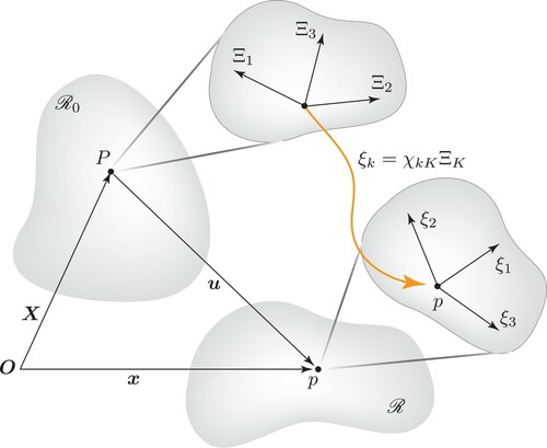
Figure 2. Two-dimensional vortex field configurations with various integers N using (Equation34(34)
(34) ) and its corresponding
fields on
of (Equation42
(42)
(42) ) are shown where
is essentially the isotropic distribution of the hedgehog configuration
.
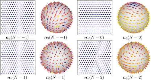
Figure 3. The correspondence between and its projection
is shown with the asymptotic values of
acting on the point of
. In particular, the transition of a field configuration starting from
to
is the phase rotation from zero to
on
. This is a transition that is projected on the
plane by bringing a point from infinity to the origin.
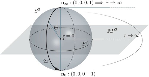
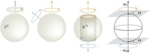
Figure 4. Suppose we have started from two states with identical spin orientations on the same axis on . As one spinor configuration undergoes a transition along the great circle, separating from the initial configuration which is kept in the initial state, the spin configuration changes gradually. When the phase reaches its
rotation, the spin configuration becomes complete opposite.