
Figures & data
Figure 1. Formation of mechanical twin by shear and definition of elements of twinning.
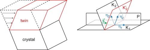
Figure 2. Crystallography of the most common twinning in fcc, schematised in (110) plane.
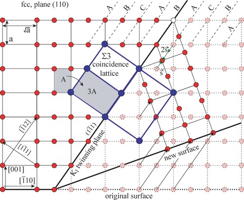
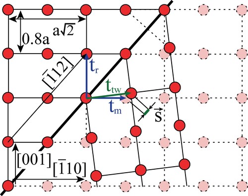
Figure 3. (a) Result of shearing by in fct lattice, c/a = 0.8. The same positions of atoms can be reached also by shearing in the opposite direction by the vector
. (b) Result of mirroring the crystal along the
plane in fct lattice, c/a = 0.8.
![Figure 3. (a) Result of shearing by s→=1/6[1¯12] in fct lattice, c/a = 0.8. The same positions of atoms can be reached also by shearing in the opposite direction by the vector s′→. (b) Result of mirroring the crystal along the (11¯1) plane in fct lattice, c/a = 0.8.](/cms/asset/bac825c5-7022-43c9-b0ca-6758de4ba578/tphm_a_2135037_f0003_oc.jpg)
Figure 4. Parameters f and f ‘ as a function of ratio r = c/a. Magnitude of the vector is the unity of the y-axis.
![Figure 4. Parameters f and f ‘ as a function of ratio r = c/a. Magnitude of the [1¯12] vector is the unity of the y-axis.](/cms/asset/8b43e0b7-e19e-4684-b33b-f1d98c215b53/tphm_a_2135037_f0004_oc.jpg)
Figure 5. The generalised planar fault energies γ (GPFE) of (a) Al, (b) In, (c) TiAl, (d) Ni2FeGa as a function of ratio (the ratio of shear displacement
and Burgers vector
. The structures in each subplot display from left to right the perfect lattice, the intrinsic stacking fault, and two- and three-layer twins. The dashed arrows correspond to the minima of non-optimised GPFE whereas solid arrows represent the minima of fully optimised GPFE. If only solid arrow is shown, both minima coincide.
![Figure 5. The generalised planar fault energies γ (GPFE) of (a) Al, (b) In, (c) TiAl, (d) Ni2FeGa as a function of |s→|/|b→| ratio (the ratio of shear displacement s→ and Burgers vector b→=1/6[1¯12]). The structures in each subplot display from left to right the perfect lattice, the intrinsic stacking fault, and two- and three-layer twins. The dashed arrows correspond to the minima of non-optimised GPFE whereas solid arrows represent the minima of fully optimised GPFE. If only solid arrow is shown, both minima coincide.](/cms/asset/c5606412-beb0-4fc6-ad6a-a17fce6036a9/tphm_a_2135037_f0005_oc.jpg)
Table 1. Experimental and ab initio lattice parameters a and c/a and magnitude of Burges vector , shearing vector
, ratio
, and factor f calculated from ab initio lattice parameters. The experimental data were taken from the following works: Al [Citation71]; In [Citation72]; TiAl [Citation73]; Ni2FeGa [Citation43].
Table 2. Energies of intrinsic stacking fault γisf, two-layer twin γ2t and three-layer twin γ3t in mJ/m2 and corresponding ratio of vectors and
for non-optimised and fully-optimised structures.
Figure A1. Geometry of mirror-type twin in fct lattice with lattice constants a and c.
Data availability
Data will be made available on request.