
Figures & data
Table 1. The grain boundary mobility during nucleus growth used in the simulation [Citation64–69].
Figure 1. IPF map of initial samples on ND plane for (a) Ni, (b) Ni-20Fe (c) Ni-40Fe, (d) X-ray diffraction patterns, and (111) pole figure of (e) Ni, (f) Ni-20Fe, (g) Ni-40Fe.
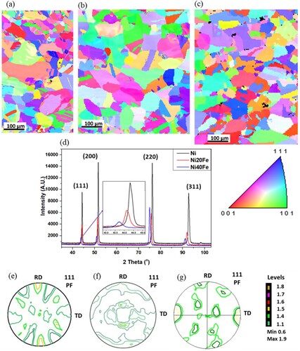
Figure 2. IPF + IQ superimposed map of 70% cold rolled (a) pure nickel, (b) Ni-20Fe, (c) Ni-40Fe. Red circled region shows the appearance of shear banding in Ni-Fe alloys. The IPF colour coding refers to a direction parallel to ND, X-ray bulk texture showing constant φ2 = 0°, 45°, 65° sections of ODF of 70% cold rolled (d) pure nickel, (e) Ni-20Fe, (f) Ni-40Fe, (g) a key ODF showing ideal texture components. Orthotropic specimen symmetry has been assumed while plotting the ODFs from experimental pole figures.
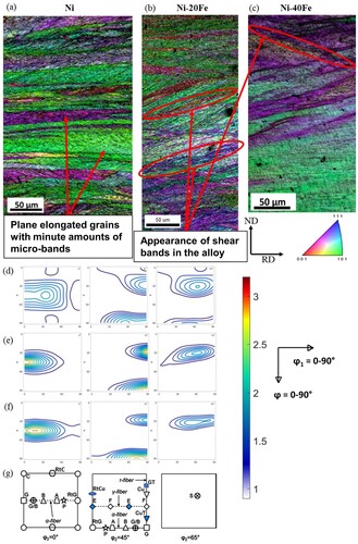
Figure 3. The constant φ2 = 0°, 45°, 65° sections of ODF of (a) Ni 20% recrystallized (75 s annealing), (b) Ni 100% recrystallized (120 s annealing), (c) Ni-20Fe 20% recrystallized (135 s annealing), (d) Ni-20Fe 100% recrystallized (180 s annealing), (e) Ni-40Fe 20% recrystallized (135 s annealing), (f) Ni-40Fe 100% recrystallized (180 s annealing), (g) a key ODF showing the location important texture components (C – cube, G – Goss, Cu – Copper, B – Brass). Orthotropic specimen symmetry was assumed while plotting the ODFs.
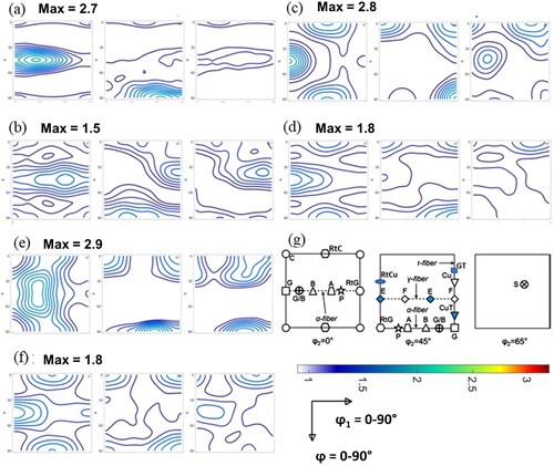
Table 2. Comparison of Ni and Ni-Fe alloy for change in volume fraction of important texture components as a function of recrystallization.
Figure 4. IPF + IQ superimposed map of 70% cold-rolled, Ni after (a) 60 s, (b) 75 s, (c) 105 s, Ni-20Fe after (d) 120 s, (e) 150 s, (f) 480 s, Ni-40Fe after (g) 120 s, (h) 150 s, (i) 480 s, annealing at 700°C. Orange arrows indicate Gb nucleation, red circled regions indicate shear band nucleation and growth along it, yellow circle shows the formation of annealing twins. The IPF colour coding refers to a direction parallel to ND.
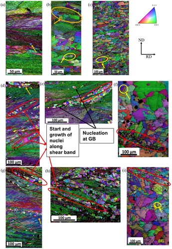
Figure 5. Grain boundaries misorientation profile of 70% cold-rolled material as a function of annealing time (a) pure Ni, (b) Ni-20Fe, and (c) Ni-40Fe, bar plot showing the grain boundaries character distribution (CSLs boundaries) of 70% cold-rolled material as a function of annealing time (d) pure Ni, (e) Ni-20Fe and (f) Ni-40Fe. It shows that all the stages of recrystallization are dominated by the formation of 1st and higher-order twin boundaries.
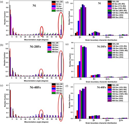
Figure 6. CSLs distribution superimposed on IQ maps of 25% recrystallized, (a) Ni, (b) Ni-20Fe, (c) Ni-40Fe, (d) a schematic representation of different type of Σ3 based on their shape within a grain (a-h). For each type of boundary, a representative name has also been given.
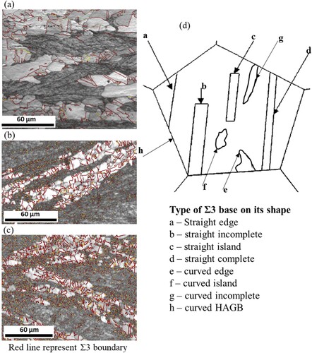
Figure 7. Grain boundary plane distribution associated with Σ3 (111/60°) misorientation in pure Ni (a) 25% RX, (b) 100% RX, in Ni-20Fe (c) 25% RX, (d) 100% RX, in Ni-40Fe (e) 25% RX, (f) 100% RX (g) stereographical representation of calculated geometrically characteristic boundaries associated with Σ3 (111/60°) misorientation.
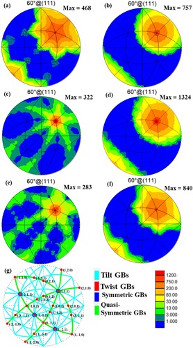
Figure 8. Simulated Inverse pole figure (IPF) map of 70% rolled pure Ni at different level of recrystallization at 700°C (a) 10%, (b) 30%, (c) 50%, (d) 80%, (e) 100% recrystallized, (f) experimental IPF map of 100% recrystallized pure Ni, for comparison, IPF map of Ni-20Fe after full recrystallization (g) simulated, (h) experimental, and simulated IPF map of Ni-40Fe after full recrystallization (i) simulated, (j) experimental, for comparison.
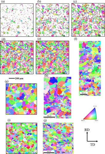
Figure 9. Comparison of the constant φ2 = 0°, 45°, and 65° sections of ODF of 100% recrystallized pure Ni (a) experimental, (b) simulated, Ni-40Fe (c) experimental, (d) simulated, (e) a key ODF showing the location important texture components (G – Goss, Cu – Copper, Bs – Brass).
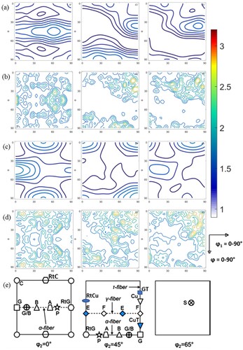
Figure 10. Variation of volume fraction of all the orientations present (more than 2%) in rolled and annealed pure Ni (a) 70% CR and 18% recrystallized, (b) 70% CR and 60% recrystallized, (c) 70% CR and 100% recrystallized, (d) 18% and 100% recrystallized, in Ni-20Fe (e) 70% CR and 12% recrystallized, (f) 70% CR and 25% recrystallized, (g) 70% CR and 100% recrystallized, (h) 25% and 100% recrystallized, in Ni-40Fe (i) 70% CR and 10% recrystallized, (j) 70% CR and 40% recrystallized, (k) 70% CR and 100% recrystallized, (l) 40% and 100% recrystallized, samples, respectively, calculated through TSL OIM8.2.
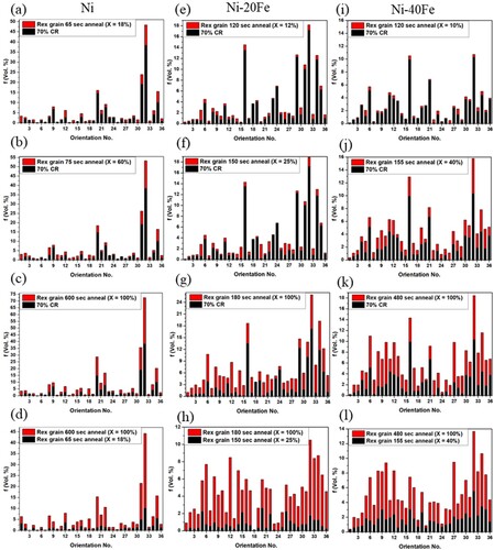
Table 3. All orientation components observed in deformed and recrystallized material along with their miller indices and Euler angle in Bunge notation.
Figure 11. Nucleation at GB and transition band intersection, (a) IPF map of Ni 70%CR 65 s anneal sample, (b) nuclei partitioned based on GOS value, (c) enlarged view of one of the nuclei and their neighbours showing two deformed grain (D1 and D2) in both sides of nuclei, and two sub-grain (S1 and S2), (d) (111) pole figure showing the orientation of D1, D2, S1, and S2, (e) enlarged view of other nuclei and their neighbours showing three deformed grain (D3, D4, and D5) in the neighbour of nuclei, and subgrain (S3) (probable nuclei), (f) (111) pole figure showing the orientation of D3, D4, D5, and S3. Based on misorientation profile sub-grain S1 and S3 were found to grow as successful nuclei N1 and N2, respectively.
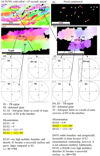
Figure 12. Nucleation at GB and transition band intersection, 3D IPF map of (a) pure Ni 70%CR, (b) Ni 70% CR 60 s anneal, (c) sectioned view of 60 s anneal sample indicating the region of nucleation, 3D GROD map of (d) pure Ni 70%CR, (e) Ni 70% CR 60 s anneal, (f) sectioned view of 60 s anneal sample indicating the region of nucleation (blue colour).
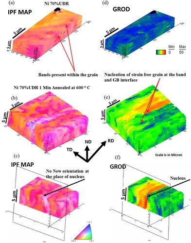
Figure 13. Growth of nuclei at the grain boundary, (a) IPF map of Ni 70%CR 105 s anneal sample, each grain is numbered (1–39), the black line shows Σ3 (<111>/60°) boundary, and the white line shows Σ9 boundaries, twin (Σ3) plane trace analysis of Σ3 boundary between (b-d) grain 2 and 3 (2–3 Σ3 boundary), (e-g) grain 5 and 7 (5-6-7 Σ3 boundary).
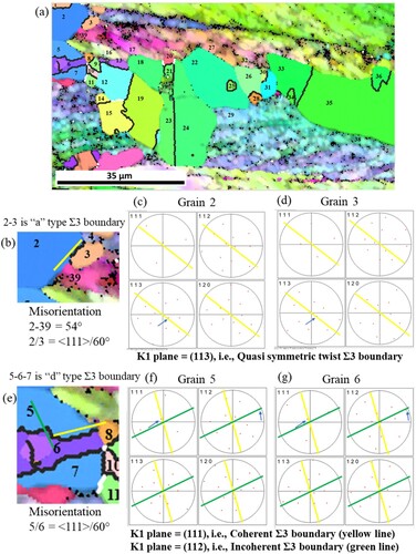
Table 4. Type of different Σ3 (<111>/60°), and Σ9 (<110>/38.9°) boundary present during the growth of nuclei in , their corresponding K1 plane and the characteristics grain boundary character.
Table 5. Frequency of occurrence of different types of Σ3 Boundary (<111>/60°) based on their shape as presented in . The data shown here is for the growth of nuclei during the very initial stage of recrystallization.