Figures & data
Figure 1. Logical diagram of the research.
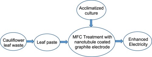
Table 1. List of abbreviations and symbols used in this manuscript.
Table 2. Physiochemical parameters of cauliflower waste sample.
Figure 2. Open circuit voltage (OCV) observed during microbial fuel cell (MFC) operation at different time intervals. MFC was operated with normal graphite and polyaniline multiwalled carbon nanotubule (PANI/MWCNT)-coated graphite for analysis.
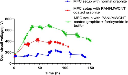
Table 3. OCV developed and power density during the MFC operation.
Figure 3. Power generation in a microbial fuel cell using polyaniline multiwalled carbon nanotubule (PANI/MWCNT)-coated graphite fibre with the addition of potassium ferricyanide in catholyte and external resistance of 1000 and 100 Ω.
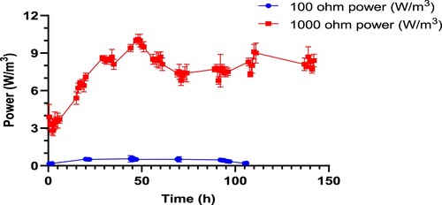
Table 4. Change in different chemical parameters of the substrate after MFC operation.
Figure 4. Scanning electron microscopy (SEM) images of the graphite electrode. A: Normal graphite electrode; B: polyaniline multiwalled carbon nanotubule (PANI/ MWCNT)-coated graphite electrode and; C: PANI/MWCNT-coated graphite electrode after microbial fuel cell operation.
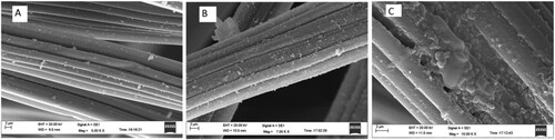
Figure 5. Holozone test for cellulolytic bacteria in carboxymethyl cellulose (CMC) agar plate by isolates R2, R3 and R4 (left to right) showing cellulolytic activity.
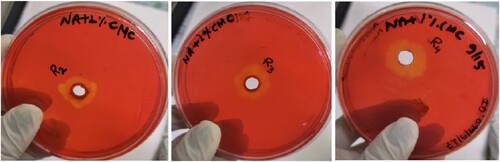
Figure 6. Gel electrophoresis of molecular amplification of 16S rRNA gene of bacterial DNA using a universal primer (1500 bp) in 1% agarose gel. L1: R2 bacteria, L2: R3 bacteria, L3: R4 bacteria and L4: ladder 100 bp.
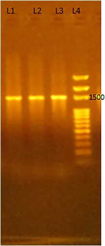
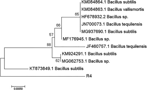
Figure 7. Phylogenetic tree of R4 obtained by the neighbour-joining method using MEGA software. The efficiency of tree resolution was considered successful only when the clades have at least >50% bootstrap value. The allocated gene bank accession number of the R4 isolate is MT040749.