Figures & data
Figure 1. Model representation of the proposed network.
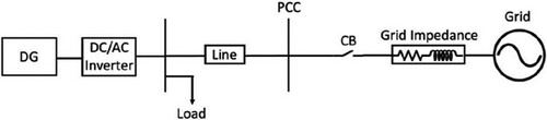
Figure 2. Three-phase inverter and its control structure.
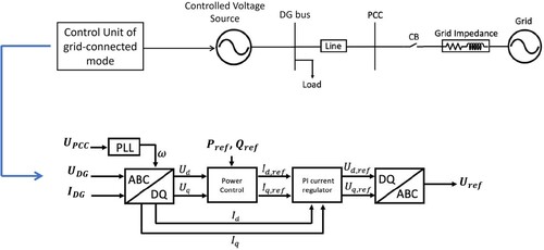
Figure 3. Turn-off mode and V/f control mode of the three-phase inverter.
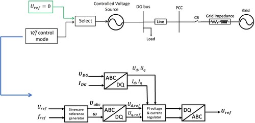
Figure 4. Switch operation and fault detection scheme representation.
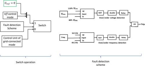
Figure 5. Rotating reference frame.
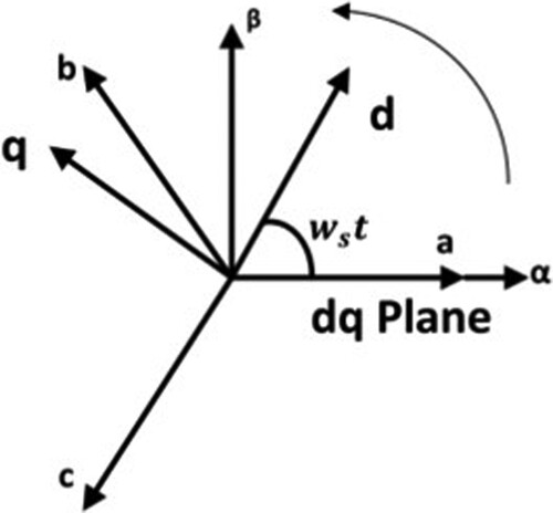
Table 1. Model parameters.
Figure 6. Active/reactive power, voltage and frequency at the DG bus during normal operating conditions.
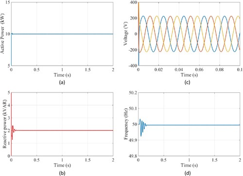
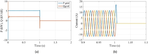
Figure 7. Active/reactive power, voltage and current at PCC during normal operating conditions.
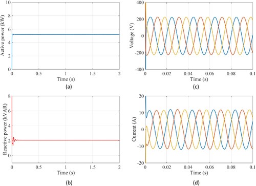
Figure 8. Active/reactive power, voltage and frequency at DG bus during switch-off mode.
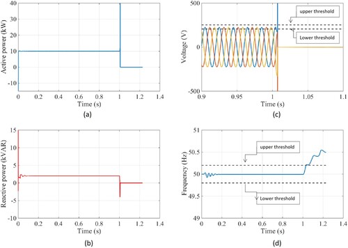
Figure 9. Active/reactive power, current and trip signal at PCC during switch-off mode.
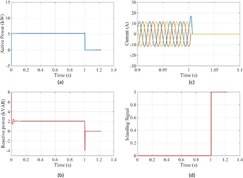
Figure 10. Active/reactive power, voltage, frequency and trip signal at DG bus during V/f control mode.
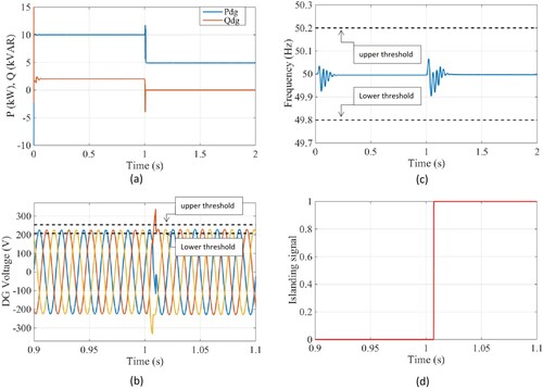
Figure 11. Active/reactive power, current at PCC during V/f control mode.