
Figures & data
Figure 1. The device structure of (a) HTM&CNT, (b) HTM/CNT, and (c) energy level of P3HT (left) (Ye et al. Citation2016) and NiOx (right)-based (Yin et al. Citation2017) PSCs.
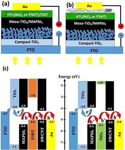
Figure 2. FESEM top views of (a) perovskite film applied on a TiO2 mesoporous layer, (b) NiOx film on perovskite (c), and (d) P3HT film on perovskite (e) NiOx&CNT layer on perovskite, (f) NiOx/CNT layer on perovskite (g) P3HT&CNT layer on perovskite, (h) P3HT/CNT layer on perovskite. The scale bar corresponds to 500 nm. Cross-sectional FESEM image of the perovskite solar devices based on (i) NiOx/CNT, and (j) P3HT&CNT (a)-(i) are secondary electron images, (j) is a backscattered electron image. The scale bar corresponds to 250 nm.
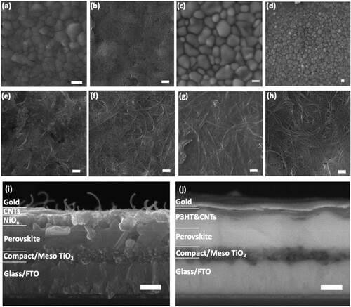
Figure 3. UV-Vis absorption spectra of (a) NiOx-based and (b) P3HT-based HTMs deposited on FTO/C-TiO2/Meso-TiO2/Perovskite structure. Photoluminescence spectra of (c) NiOx-based, and (d) P3HT-based devices on the glass/perovskite films.
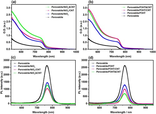
Figure 4. Nyquist plots of the devices with (a) NiOx/CNT and (b) P3HT&CNT HTMs for different applied bias, and (c) comparison between Nyquist plots of devices using NiOx, P3HT, NiOx/CNT and P3HT&CNT as HTM, under illumination at the biased voltage of 0.8 V (inset: the equivalent circuit model used for EIS analysis).
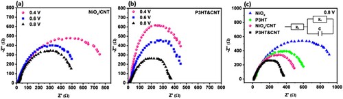
Figure 5. J-V curves of perovskite solar devices with different HTMs a) P3HT and b) NiOx, after 8 days of fabrication kept at room temperature, 35-40% RH, and dark condition. and (c) comparison of photoconversion efficiency of NiOx, P3HT, NiOx /CNT and P3HT&CNT devices during 90 days.
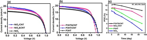
Table 1. Photovoltaic parameters of the perovskite solar devices with different HTMs, 8 devices were used for each condition.
gsol_a_2204363_sm3100.docx
Download MS Word (155.5 KB)Data availability
Data is available on request from the authors.
