
Figures & data
Table 1. Kinetic façade active materials and identification of their function (Marysse Citation2015).
Table 2. Literature review summary and findings.
Figure 1. Dubai frame location map (Authors).
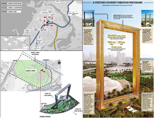
Figure 2. Research approach methodological framework (Authors).
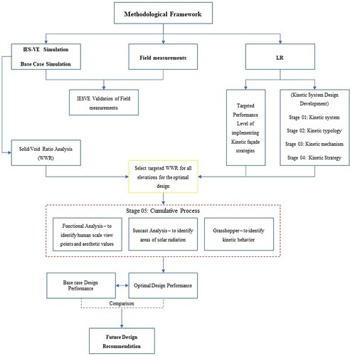
Figure 3. Dubai Frame field measurements locations.
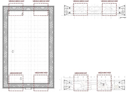
Figure 4. Total electricity validation and discrepancy percentage.
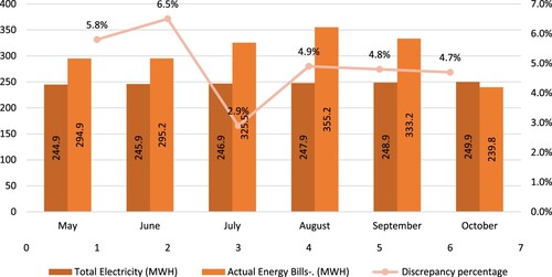
Table 3. Base case construction materials.
Figure 5. Total daylight validation measures.
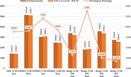
Figure 6. Total electricity as a result of adjusting the facade WWR.
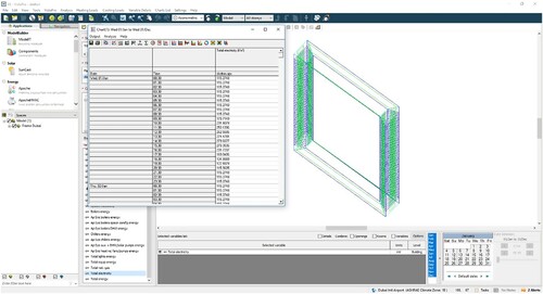
Table 4. Mezzanine Floor and Viewing Bridge luminance and radiance contour images.
Table 5. Viewing Bridge luminance and radiance contour images at 12:00 PM.
Table 6. Dubai frame elevations and the proposed façade.
Table 7. Proposed kinetic movement/south and north façade.
Table 8. Proposed kinetic movement/east and west façade (Authors).
Figure 7. Adjustments to glazing area through IES VE to identify the reduction in total electricity.
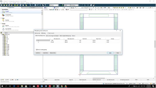
Figure 8. The complete script of the parametric model in Grasshopper.
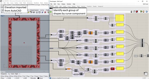
Figure 9. Void area parametric model script.
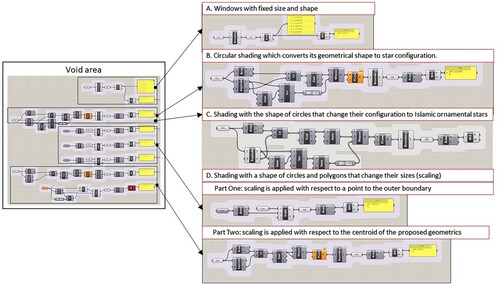
Figure 10. Circular shading to star configuration movement mechanism.
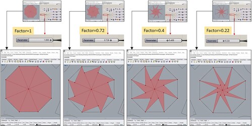
Table 9. An example for the sun exposure analysis of the south façade to be used for WWR selection.
Table 10. Dubai Frame Viewing Bridge and Mezzanine exhibition stands.
Table 11. Optimal WWR as a result of the aesthetic performance-based design strategy (Authors).
Figure 11. Shading with a shape of circles and polygons based on its own centroid.
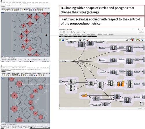
Figure 12. Total electricity and cooling loads for SIM 1–9.
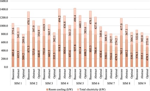
Figure 13. The average electricity savings of the optimal design from 8:30 AM to 17:30 PM.
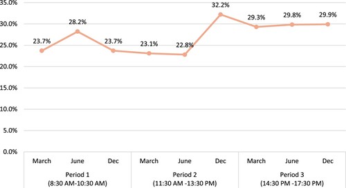
Table 12. A summary of the annual electricity and cooling loads for the base case, abstract and the optimal design.
Figure 14. Base case and optimal design illuminance levels of SIM 1–9/Mezzanine floor and Viewing Bridge.
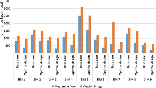
Table A1. SIM 1 – base case vs. optimal design illuminance and radiance contour plans/Viewing Bridge.
Table A2. SIM 1 – base case vs. optimal design illuminance and radiance contour plans/Mezzanine Floor.
Table A3. SIM 2 – base case vs. optimal design illuminance and radiance contour plans/Viewing Bridge.
Table A4. SIM 2 – base case vs. optimal design illuminance and radiance contour plans/Mezzanine Floor.
Table A5. SIM 3 – base case vs. optimal design illuminance and radiance contour plans/Viewing Bridge.
Table A6. SIM 3 – base case vs. optimal design illuminance and radiance contour plans/Mezzanine Floor.
Table A7. SIM 4 – base case vs. optimal design illuminance and radiance contour plans/Viewing Bridge.
Table A8. SIM 4 – base case vs. optimal design illuminance and radiance contour plans/Mezzanine Floor.
Table A9. SIM 5 – base case vs. optimal design illuminance and radiance contour plans/Viewing Bridge.
Table A10. SIM 5 – base case vs. optimal design illuminance and radiance contour plans/Mezzanine Floor.
Table A11. SIM 6 – base case vs. optimal design illuminance and radiance contour plans/Viewing Bridge.
Table A12. SIM 6 – base case vs. optimal design illuminance and radiance contour plans/Mezzanine Floor.
Table A13. SIM 7 – base case vs. optimal design illuminance and radiance contour plans/Viewing Bridge.
Table A14. SIM 7 – base case vs. optimal design illuminance and radiance contour plans/Mezzanine Floor.
Table A15. SIM 8 – base case vs. optimal design illuminance and radiance contour plans/Viewing Bridge.
Table A16. SIM 8- Base Case vs. Optimal Design Illuminance and Radiance contour plans/Mezzanine Floor.
Table A17. SIM 9 – base case vs. optimal design illuminance and radiance contour plans/Viewing Bridge.
Table A18. SIM 9 – base case vs. optimal design illuminance and radiance contour plans/Mezzanine Floor.