Figures & data
Figure 1. Wind Tunnel Test Setup, Key Dimensions, and Installation Connection Method.
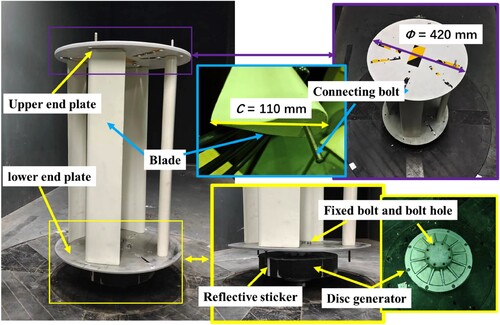
Figure 2. The designed airfoil with curvature (green coordinate line).
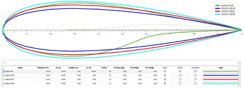
Figure 3. Comparison curves of lift coefficient (a) and lift-to-drag ratio variation (b) for the experimental blade (the red curve represents the airfoil used in the experiment).
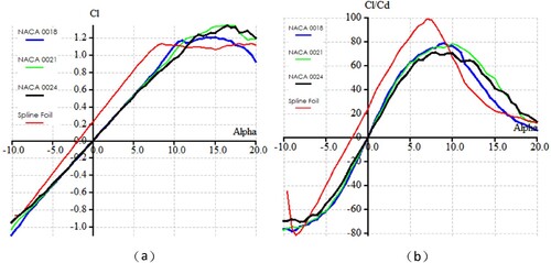
Figure 4. The variable initial installation angle of the blades (a), as well as the forward (b) and reverse (c) blade installation configurations.
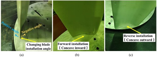
Figure 5. Physical image of blades with different lengths.
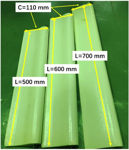
Figure 6. The closed-loop wind tunnel at Shanghai Maritime University (a), and external six-component force balance device (b).
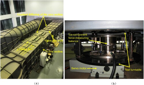
Figure 7. Balance force measurement coordinate system in wind tunnel at 0-degree azimuth angle.
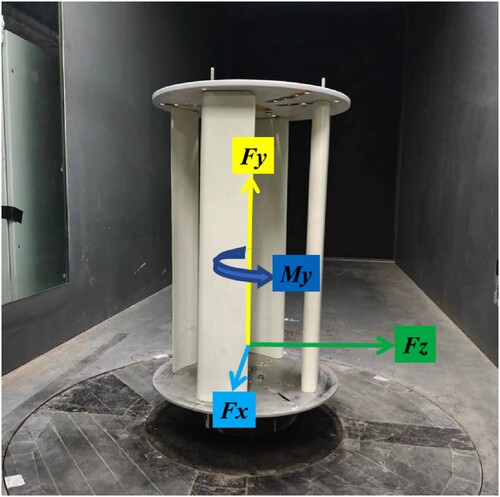
Figure 8. The curve of wind turbine rotational speed with wind speed variation under forward and reverse blade installations.
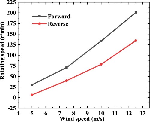
Figure 9. The lift variation curve (a) and the drag variation curve (b) of the wind turbine under different wind speeds for both forward and reverse blade installations.
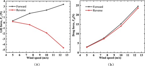
Figure 10. the torque variation curves of a wind turbine under different wind speeds for both the forward and reverse blade installation modes.
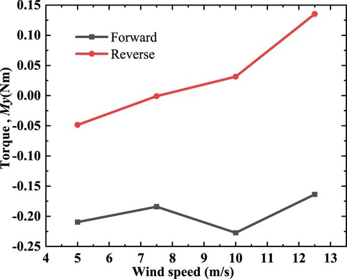
Figure 11. the curve of wind turbine rotational speed variation with different installation angles at various wind speeds.
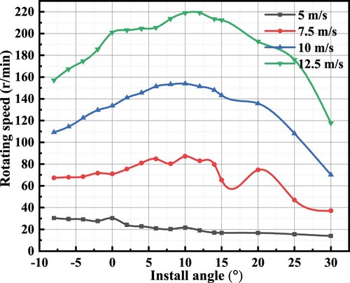
Figure 12. The variation curves of lift (a) and drag (b) of the wind turbine with different installation angles at various wind speeds.
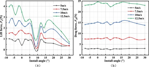
Figure 13. the curve of the variation of wind turbine torque with different installation angles at various wind speeds.
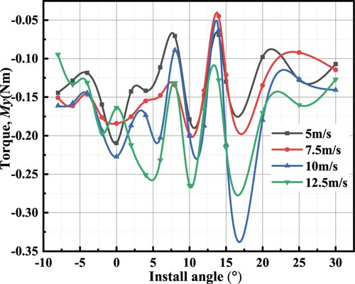
Figure 14. The comparative diagram of the rotational speed of wind turbines with two different installation radii under various wind speeds.
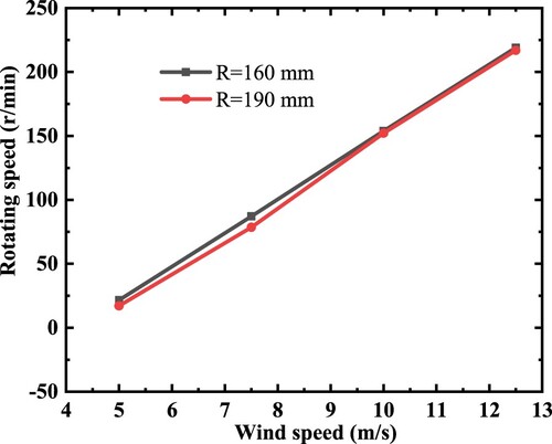
Figure 15. The comparative diagram of lift and drag for wind turbines with two different installation radii.
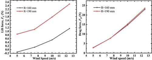
Figure 16. The comparative diagram of the change in torque of wind turbines with two different installation radii as a function of wind speed.
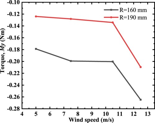
Figure 17. The comparative diagram of wind turbine rotational speed at different wind speeds for different blade lengths.
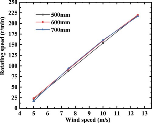
Figure 18. The curves of wind turbine lift (a) and drag (b) with wind speed for installation of blades with different lengths.
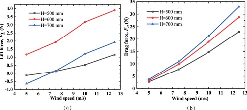
Figure 19. the comparison diagram of torque variations with wind speed for wind turbines with different blade lengths.
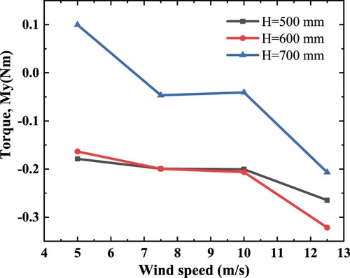
Figure 20. The comparison curve of wind turbine speed with and without a 10 Ω load at different wind speeds.
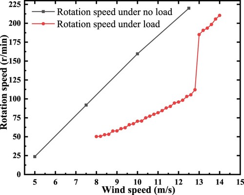
Figure 21. The Variation curves of fixed resistance load voltage (A) and current (B) with wind speed at different wind speeds.
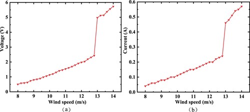
Figure 22. The torque variation curves of a wind turbine with a resistive load and an unloaded condition at different wind speeds.
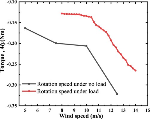
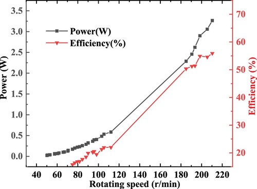
Figure 23. The variations in power output and electrical generation efficiency of a wind turbine device at different rotational speeds.