Figures & data
FIGURE 1. Topology of the DC–DC SBDO converter designed to support the balancing of bipolar DC microgrids.
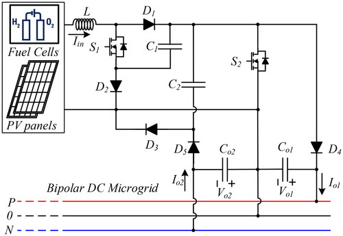
FIGURE 2. First (a) and second (b) operation modes of the SBDO converter designed to be used in bipolar DC microgrids.
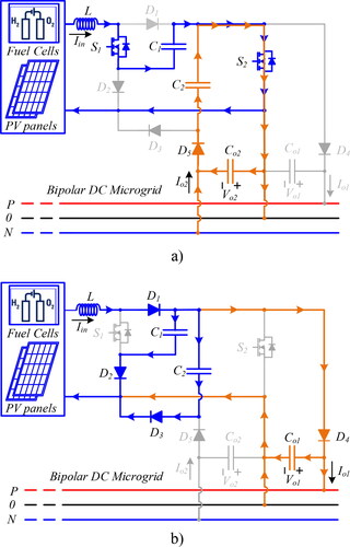
FIGURE 3. Current and voltage waveforms associated to the CCM of the proposed SBDO converter to be used in bipolar DC microgrids.
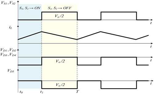
FIGURE 4. Comparison of the static input-to-output voltage gain function of the duty cycle between the classical Boost, the dual Boost, the Z-source converter, and the proposed SBDO converter.
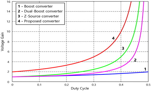
FIGURE 5. Results obtained by simulation of the SBDO converter designed for the bipolar DC microgrid: (a) voltages of the input source and SBDO converter output; (b) voltages over transistors S1 and S2; (c) input current of the proposed SBDO converter.
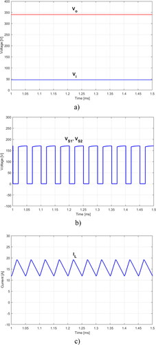
FIGURE 6. Results obtained by simulation of the SBDO converter designed for the bipolar DC microgrid when there is a suddenly change in the load connected to the negative pole: (a) Output currents of the proposed SBDO converter and (b) voltages across capacitors C1 and C2.
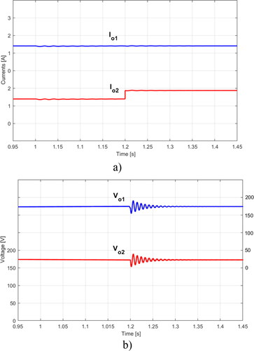
FIGURE 7. Results obtained through laboratory tests of the SBDO converter designed for the bipolar DC microgrid: (a) voltages of the input source and SBDO converter output; (b) voltages over transistors S1 and S2; (c) input current of the proposed SBDO converter.
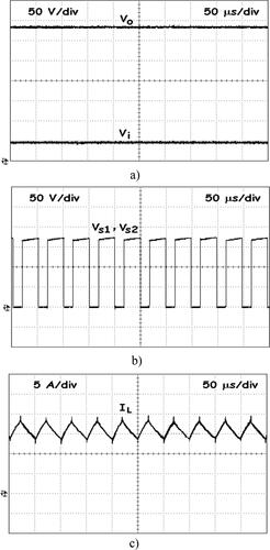
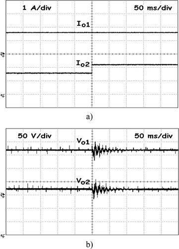
FIGURE 8. Results obtained through laboratory tests of the SBDO converter designed for the bipolar DC microgrid when there is a suddenly change in the load connected to the negative pole: (a) Output currents of the proposed SBDO converter and (b) voltages across capacitors C1 and C2.