
Figures & data
Figure 1. Multi-Layers Insulated Sandwich Panel with Shear Connectors (Insulated cores are removed for illustration purpose).
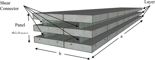
Figure 2. Box plate-section with shear connectors for multi-layers sandwich panel.
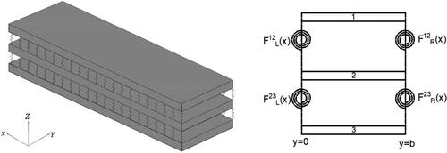
Figure 3. Slip between layers.
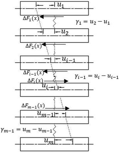
Figure 4. Strain distribution.
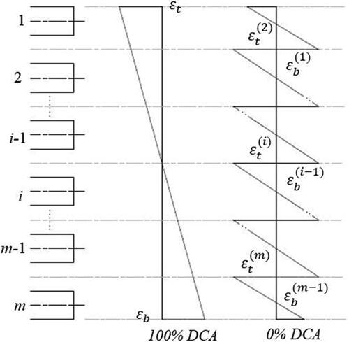
Figure 5. Axial and bending moment on multi-layers sandwich panel.
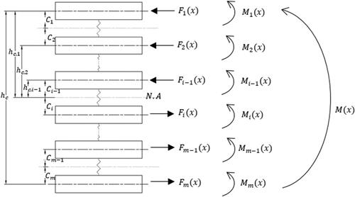
Figure 6. Shear force distribution on 5-layers sandwich panel (a) side view, (b) plate-section, (c) typical shear force diagram.
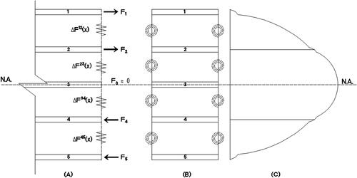
Figure 7. WF section.
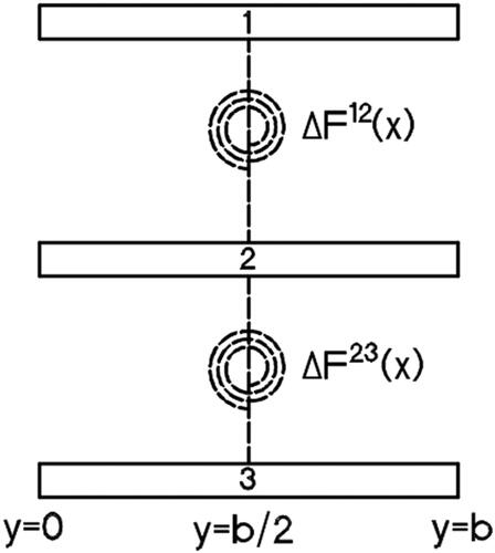
Figure 8. Multi-cell box section [Citation10].
![Figure 8. Multi-cell box section [Citation10].](/cms/asset/c2ac73f2-20df-4af1-a3c4-b117c3df2b12/umcm_a_1998736_f0008_b.jpg)
Figure 9. FE model for 4-layers 2-cell sandwich panel.
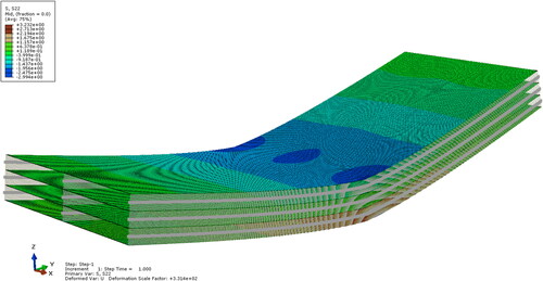
Table 1. Shear connector stiffness for single box.
Table 2. Shear connector stiffness for WF.
Table 3. Shear connector stiffness for cantilever.
Table 4. Shear connector stiffness for 2-cell.
Figure 10. Stress distribution for 3-layers (single box).
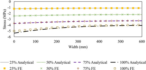
Figure 11. Stress distribution for 3-layers (WF).
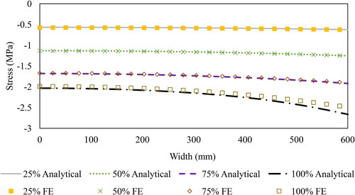
Figure 12. Stress distribution for 3-Layers (Cantilever).
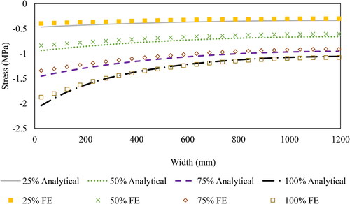
Figure 13. Stress distribution for 3-layers (2-Cell).
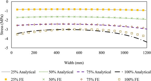
Figure 14. Connector shear forces for 4-layers (2-cell) with different DCA: (a) 100%, (b) 75%, (c) 50% and (d) 25%.
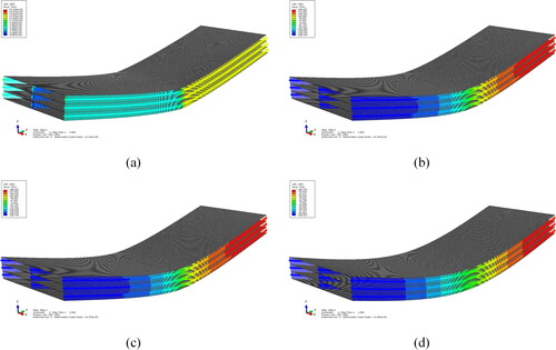
Figure 15. Connector shear forces for 4-layers (2-cell) with 100% DCA (Layer elements are not shown for clarity).
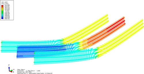
Table 5. Average stress for single box (MPa).
Table 6. Average stress for WF (MPa).
Table 7. Average stress for cantilever (MPa).
Table 8. Average stress for 2-cell (MPa).
Figure 16. Mid-span deflection of 2-cell for multi-layers configurations.
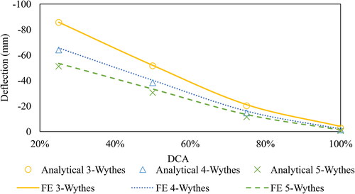
Figure 17. Geometry of multi-layers.
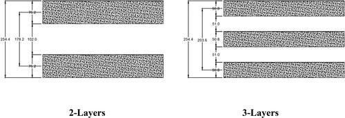
Table 9. Geometry of different number of layers.
Figure 18. Pressure load applied.
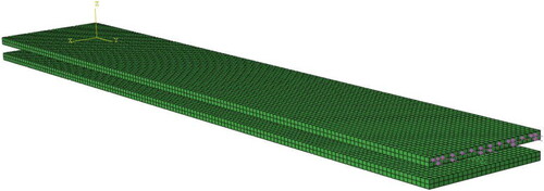
Figure 19. CFRP geometry.
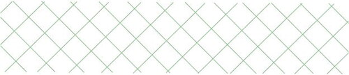
Table 10. Material properties.
Figure 20. Deflection of multi-layers with CFRP shear connector.
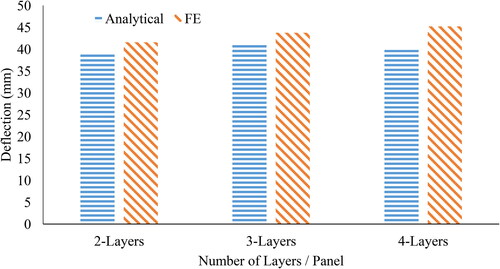
Figure 21. Stress on top surface of multi-layers with CFRP shear connector.
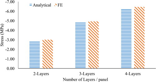
Table 11. Shear stiffness of multi-layers sandwich panels.
Table 12. Deflection and stress results of multi-layers with CFRP.