3,070
Views
37
CrossRef citations to date
0
Altmetric
Extra Views

Genomic and chromatin features shaping meiotic double-strand break formation and repair in mice

ORCID Icon, ORCID Icon, ORCID Icon, , & ORCID Icon
Pages 1870-1884 | Received 28 Apr 2017, Accepted 25 Jul 2017, Published online: 14 Sep 2017

Figures & data

Figure 1. Spatial relationships between H3K36 trimethylation and DSBs. (A) H3K36me3 (data from Citationref. 32) has a similar profile as H3K4me3 (data from Citationref. 22) around SPO11-oligo hotspots. Data were locally normalized by dividing the signal at each base pair (bp) by the mean signal within each 2,001-bp window, then were averaged across hotspots. The SPO11-oligo profile was smoothed with a 51-bp Hann filter. The central SPO11-oligo peak is cut off for clarity in presenting the spacing of the subsidiary peaks; the central peak's maximum value is 26. (B) H3K36me3 signal is often highly asymmetric around hotspots in a manner similar to H3K4me3. Heat maps (data in 5-bp bins after local normalization) were ordered according to H3K4me3 asymmetry. Because data in each hotspot were locally normalized, color-coding reflects the local spatial pattern, not relative signal strength between hotspots. (C) Similar asymmetric patterns between H3K4me3 and H3K36me3 at SPO11-oligo hotspots. Each panel shows the mean of locally normalized profiles (51-bp Hann filter for SPO11-oligo data) across the 20% of hotspots with the most asymmetric H3K4me3 patterns (left > right in top panel; right > left in bottom panel). The maximum values of the SPO11-oligo profiles were both 28. (D) In 3 classes of PRDM9 motifs previously defined according to local SPO11-oligo pattern,Citation26 H3K36me3 patterns are similar. The sequence logo shows the 12-bp core PRDM9 motif identified by MEME within SPO11-oligo hotspots;Citation26 the light green bar denotes the larger 36-bp segment of DNA thought to be bound by PRDM9.Citation21,Citation29 Data were locally normalized by dividing the signal at each base pair by the mean signal within each 501-bp window, then were averaged across hotspots. SPO11-oligo profiles were smoothed with a 15-bp Hann filter. (E) Similar H3K36me3 signal strength for hotspots in each of the 3 PRDM9 motif classes, as observed for H3K4me3. H3K4me3 tag counts and H3K36me3 coverage were summed in 1,001-bp windows around hotspot centers. Tag count is the sum of reads that overlap the window; coverage is the sum of total read coverage across the window. Different measurement units were used here because of differences in the data sources: original H3K4me3 data from Citationref. 22 were re-mapped,Citation26 whereas the published H3K36me3 coverage map from Citationref. 32 was used directly. In the box plots, thick horizontal lines indicate medians, box edges show the 25th and 75th percentiles, and whiskers indicate lowest and highest values within 1.5-fold of the interquartile range; outliers are not shown. A value of 1 was added to each hotspot to permit plotting of hotspots with no H3K4me3 or H3K36me3 signal. (F) H3K36me3 is an imperfect predictor of DSB frequency. SPO11-oligo counts and H3K36me3 coverage were summed in 1,001-bp windows around hotspot centers. One H3K36me3 count was added to each hotspot to permit plotting of hotspots with no H3K36me3 signal. (G and H) The effect of ATM deficiency on hotspot activity is independent of H3K4me3 levels. H3K4me3 tag counts and SPO11-oligo counts in B6, Atm null, and Atm wt were summed in 1,001-bp windows around B6 hotspot centers. The ratio of SPO11-oligo counts in Atm null to Atm wt was plotted against SPO11-oligo counts in B6 (G) or H3K4me3 counts (H). One count was added to each hotspot in Atm null and Atm wt SPO11-oligo data and H3K4me3 data to permit plotting of hotspots with no signal. (I) Fit of a multiple regression model predicting SPO11-oligo counts in hotspots from H3K4me3, H3K36me3, and Atm null:Atm wt ratio. Predicted SPO11-oligo counts were calculated for all hotspots by inputting the observed values of H3K4me3, H3K36me3 and Atm null:Atm wt ratio to the multiple regression model (Table S1). Panels depicting SPO11-oligo and H3K4me3 ChIP data were adapted from Citationref. 26 with permission. In panels showing H3K36me3 signal around SPO11-oligo hotspots and PRDM9 motifs, data were plotted starting from values of 0.56 (A and C) or 0.36 (D) to facilitate side-by-side comparison with H3K4me3 data. All R2 values were determined by linear regression on log-transformed data.
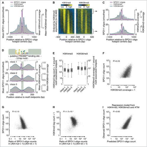
Figure 1. Spatial relationships between H3K36 trimethylation and DSBs. (A) H3K36me3 (data from Citationref. 32) has a similar profile as H3K4me3 (data from Citationref. 22) around SPO11-oligo hotspots. Data were locally normalized by dividing the signal at each base pair (bp) by the mean signal within each 2,001-bp window, then were averaged across hotspots. The SPO11-oligo profile was smoothed with a 51-bp Hann filter. The central SPO11-oligo peak is cut off for clarity in presenting the spacing of the subsidiary peaks; the central peak's maximum value is 26. (B) H3K36me3 signal is often highly asymmetric around hotspots in a manner similar to H3K4me3. Heat maps (data in 5-bp bins after local normalization) were ordered according to H3K4me3 asymmetry. Because data in each hotspot were locally normalized, color-coding reflects the local spatial pattern, not relative signal strength between hotspots. (C) Similar asymmetric patterns between H3K4me3 and H3K36me3 at SPO11-oligo hotspots. Each panel shows the mean of locally normalized profiles (51-bp Hann filter for SPO11-oligo data) across the 20% of hotspots with the most asymmetric H3K4me3 patterns (left > right in top panel; right > left in bottom panel). The maximum values of the SPO11-oligo profiles were both 28. (D) In 3 classes of PRDM9 motifs previously defined according to local SPO11-oligo pattern,Citation26 H3K36me3 patterns are similar. The sequence logo shows the 12-bp core PRDM9 motif identified by MEME within SPO11-oligo hotspots;Citation26 the light green bar denotes the larger 36-bp segment of DNA thought to be bound by PRDM9.Citation21,Citation29 Data were locally normalized by dividing the signal at each base pair by the mean signal within each 501-bp window, then were averaged across hotspots. SPO11-oligo profiles were smoothed with a 15-bp Hann filter. (E) Similar H3K36me3 signal strength for hotspots in each of the 3 PRDM9 motif classes, as observed for H3K4me3. H3K4me3 tag counts and H3K36me3 coverage were summed in 1,001-bp windows around hotspot centers. Tag count is the sum of reads that overlap the window; coverage is the sum of total read coverage across the window. Different measurement units were used here because of differences in the data sources: original H3K4me3 data from Citationref. 22 were re-mapped,Citation26 whereas the published H3K36me3 coverage map from Citationref. 32 was used directly. In the box plots, thick horizontal lines indicate medians, box edges show the 25th and 75th percentiles, and whiskers indicate lowest and highest values within 1.5-fold of the interquartile range; outliers are not shown. A value of 1 was added to each hotspot to permit plotting of hotspots with no H3K4me3 or H3K36me3 signal. (F) H3K36me3 is an imperfect predictor of DSB frequency. SPO11-oligo counts and H3K36me3 coverage were summed in 1,001-bp windows around hotspot centers. One H3K36me3 count was added to each hotspot to permit plotting of hotspots with no H3K36me3 signal. (G and H) The effect of ATM deficiency on hotspot activity is independent of H3K4me3 levels. H3K4me3 tag counts and SPO11-oligo counts in B6, Atm null, and Atm wt were summed in 1,001-bp windows around B6 hotspot centers. The ratio of SPO11-oligo counts in Atm null to Atm wt was plotted against SPO11-oligo counts in B6 (G) or H3K4me3 counts (H). One count was added to each hotspot in Atm null and Atm wt SPO11-oligo data and H3K4me3 data to permit plotting of hotspots with no signal. (I) Fit of a multiple regression model predicting SPO11-oligo counts in hotspots from H3K4me3, H3K36me3, and Atm null:Atm wt ratio. Predicted SPO11-oligo counts were calculated for all hotspots by inputting the observed values of H3K4me3, H3K36me3 and Atm null:Atm wt ratio to the multiple regression model (Table S1). Panels depicting SPO11-oligo and H3K4me3 ChIP data were adapted from Citationref. 26 with permission. In panels showing H3K36me3 signal around SPO11-oligo hotspots and PRDM9 motifs, data were plotted starting from values of 0.56 (A and C) or 0.36 (D) to facilitate side-by-side comparison with H3K4me3 data. All R2 values were determined by linear regression on log-transformed data.

Figure 2. Sequence composition at sites of SPO11-oligo formation and 3′ nicking. (A, top) Schematic of a SPO11 DSB. Staggered cuts (arrows) by a SPO11 dimer generate 2-nucleotide 5′ overhangs, in the middle of which is a 2-fold axis of rotational symmetry; (bottom) non-random dinucleotide composition around SPO11 cleavage sites in 9,060 SPO11-oligo hotspots. At each position, deviation of dinucleotide frequencies from local average was summed. (B) Mononucleotide composition around the 5′ ends of uniquely mapped SPO11 oligos within hotspots. Purple, all cleavage sites; blue, SPO11 oligos with the 5′-mapped end in a PRDM9 motif and without a 5′ C; red, SPO11 oligos without an overlap to a PRDM9 motif and without a 5′ C. Plots are truncated for values outside of the range from -1 to 1. (C) Dinucleotide base composition is not rotationally symmetric around the dyad axis. The dinucleotide composition on the left of cleavage sites was compared with the composition on the right for each of the 256 possible dinucleotide pairs. The correlation coefficients (Pearson's r) were then rank-ordered and displayed as a bar plot with the 16 reverse-complementary dinucleotides (e.g., 5′-ATleft vs. 5′-TAright) colored in red. The mean ± SD of the r values is shown for reverse-complementary and non-reverse-complementary dinucleotides. (D) The distributions of 3′ ends of SPO11 oligos relative to 5′ ends are similar for the 3 classes of PRDM9 motifs defined by local SPO11-oligo pattern (see ). The 5′ and 3′ ends of SPO11-oligo profiles were smoothed with a 15-bp Hann filter.
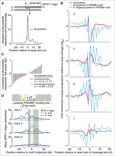
Figure 2. Sequence composition at sites of SPO11-oligo formation and 3′ nicking. (A, top) Schematic of a SPO11 DSB. Staggered cuts (arrows) by a SPO11 dimer generate 2-nucleotide 5′ overhangs, in the middle of which is a 2-fold axis of rotational symmetry; (bottom) non-random dinucleotide composition around SPO11 cleavage sites in 9,060 SPO11-oligo hotspots. At each position, deviation of dinucleotide frequencies from local average was summed. (B) Mononucleotide composition around the 5′ ends of uniquely mapped SPO11 oligos within hotspots. Purple, all cleavage sites; blue, SPO11 oligos with the 5′-mapped end in a PRDM9 motif and without a 5′ C; red, SPO11 oligos without an overlap to a PRDM9 motif and without a 5′ C. Plots are truncated for values outside of the range from -1 to 1. (C) Dinucleotide base composition is not rotationally symmetric around the dyad axis. The dinucleotide composition on the left of cleavage sites was compared with the composition on the right for each of the 256 possible dinucleotide pairs. The correlation coefficients (Pearson's r) were then rank-ordered and displayed as a bar plot with the 16 reverse-complementary dinucleotides (e.g., 5′-ATleft vs. 5′-TAright) colored in red. The mean ± SD of the r values is shown for reverse-complementary and non-reverse-complementary dinucleotides. (D) The distributions of 3′ ends of SPO11 oligos relative to 5′ ends are similar for the 3 classes of PRDM9 motifs defined by local SPO11-oligo pattern (see Fig. 1D). The 5′ and 3′ ends of SPO11-oligo profiles were smoothed with a 15-bp Hann filter.

Figure 3. DSBs in repeated sequences. (A) Five categories of SPO11-oligo mappability in “repeat” and “non-repeat” sequence classes. The repeat class schematized on the left encompasses both interspersed repeats and segmental duplications. 67.2% of SPO11 oligos could be assigned unambiguously to a unique location in the reference genome within either the non-repeat class (dark gray) or the repeat class (dark turquoise). The remaining 32.8% mapped to multiple places in the reference genome; half of these could be placed in either the non-repeat class (i.e., all mapped positions are in non-repeat sequences; light gray) or the repeat class (i.e., all mapped positions are in the repeat class; turquoise). However, the remaining half of the multi-mappers (16.3% of all mapped reads) could have derived from either class because reads mapped to both repeated and non-repeated sequences (light turquoise). (B, top) Histogram of SPO11-oligo read lengths (adapted from Citationref. 26 with permission); (bottom) percentages of the 5 categories as a function of read length. Short reads (< 20 nt) were highly enriched for multi-mapped reads, suggesting that many such SPO11 oligos were mapped to multiple places solely because of their short length. (C) Percentages of SPO11 oligos mapped to repeat sequences, estimated by 4 methods. Imputed: Reads were assigned in proportion to the number of unique reads in the neighboring area (method described in Citationref. 26). Normalized: Each multi-mapped read was divided evenly among its mapped positions. Stringent: All multi-mapped reads that could have derived from either repeat or non-repeat sequences were assigned entirely to that respective repeat class. This approach likely overestimates the DSB frequency in repeat sequences and therefore provides the most conservative estimate of the degree to which DSB formation is suppressed in repeats. Imputed read length: Because the mappability of short reads is less certain (B), we included from the imputed map only reads with lengths of 25–50 nt and recalculated the fraction of imputed reads in repeated sequences. This method represents the highest confidence estimate of the relative burden of DSBs in sequences annotated as repeats. (D) DSB frequencies in 2 sub-groups of repeat sequences. SPO11-oligo frequencies were lower than expected in interspersed repeats and in segmental duplications. (E) DSB frequencies in families of repeat sequences annotated in RepeatMasker. Overlapping repeats of the same family were merged before calculation. For each repeat family, SPO11-oligo counts per base pair were summed and their enrichment was calculated relative to expected values (estimated as described in Materials and methods). The most extreme examples are labeled, as are L1 and ERVK families, which include elements that are putative DNMT3L targets.Citation63 The identities, calculated enrichment values, and fractions of the genome occupied for all of the families analyzed are provided in Table S2. (F) Examples of individual DNA transposons with high SPO11-oligo counts. SPO11-oligo maps of unique reads or multi-mapped reads are plotted as RPM based on the total 69.4 million reads that mapped to the nuclear genome. Open bar represents MULE-MuDR (left) or hAT-Charlie (right), and filled bars represent other families of repeat sequences annotated in RepeatMasker.
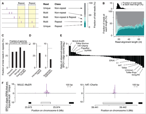
Figure 3. DSBs in repeated sequences. (A) Five categories of SPO11-oligo mappability in “repeat” and “non-repeat” sequence classes. The repeat class schematized on the left encompasses both interspersed repeats and segmental duplications. 67.2% of SPO11 oligos could be assigned unambiguously to a unique location in the reference genome within either the non-repeat class (dark gray) or the repeat class (dark turquoise). The remaining 32.8% mapped to multiple places in the reference genome; half of these could be placed in either the non-repeat class (i.e., all mapped positions are in non-repeat sequences; light gray) or the repeat class (i.e., all mapped positions are in the repeat class; turquoise). However, the remaining half of the multi-mappers (16.3% of all mapped reads) could have derived from either class because reads mapped to both repeated and non-repeated sequences (light turquoise). (B, top) Histogram of SPO11-oligo read lengths (adapted from Citationref. 26 with permission); (bottom) percentages of the 5 categories as a function of read length. Short reads (< 20 nt) were highly enriched for multi-mapped reads, suggesting that many such SPO11 oligos were mapped to multiple places solely because of their short length. (C) Percentages of SPO11 oligos mapped to repeat sequences, estimated by 4 methods. Imputed: Reads were assigned in proportion to the number of unique reads in the neighboring area (method described in Citationref. 26). Normalized: Each multi-mapped read was divided evenly among its mapped positions. Stringent: All multi-mapped reads that could have derived from either repeat or non-repeat sequences were assigned entirely to that respective repeat class. This approach likely overestimates the DSB frequency in repeat sequences and therefore provides the most conservative estimate of the degree to which DSB formation is suppressed in repeats. Imputed read length: Because the mappability of short reads is less certain (B), we included from the imputed map only reads with lengths of 25–50 nt and recalculated the fraction of imputed reads in repeated sequences. This method represents the highest confidence estimate of the relative burden of DSBs in sequences annotated as repeats. (D) DSB frequencies in 2 sub-groups of repeat sequences. SPO11-oligo frequencies were lower than expected in interspersed repeats and in segmental duplications. (E) DSB frequencies in families of repeat sequences annotated in RepeatMasker. Overlapping repeats of the same family were merged before calculation. For each repeat family, SPO11-oligo counts per base pair were summed and their enrichment was calculated relative to expected values (estimated as described in Materials and methods). The most extreme examples are labeled, as are L1 and ERVK families, which include elements that are putative DNMT3L targets.Citation63 The identities, calculated enrichment values, and fractions of the genome occupied for all of the families analyzed are provided in Table S2. (F) Examples of individual DNA transposons with high SPO11-oligo counts. SPO11-oligo maps of unique reads or multi-mapped reads are plotted as RPM based on the total 69.4 million reads that mapped to the nuclear genome. Open bar represents MULE-MuDR (left) or hAT-Charlie (right), and filled bars represent other families of repeat sequences annotated in RepeatMasker.

Figure 4. Factors influencing DSB processing. (A) Spatial correlation of SSDS coverage (data from Citationref. 21) with methylated nucleosomes. Each panel shows the mean of locally normalized profiles across the 20% of hotspots with the most asymmetric H3K4me3 patterns (left > right in top panel; right > left in bottom panel). The same local normalization factor was applied to Watson and Crick SSDS reads for each hotspot so that signal strengths on Watson and Crick were comparable. (B) Ratio of sum of locally normalized SSDS coverage in 3,001-bp windows around the centers of the subsets of hotspots from panel A. The ratios are plotted on a log2 scale but labeled according to a linear scale. The horizontal solid and dashed lines show the mean and 95% CI, respectively, estimated by bootstrap resampling from all hotspots without regard to H3K4me3 (a)symmetry. The bootstrap mean of 0.98 (-0.022 on log2 scale) is explained by the fact that the sum of locally normalized SSDS coverage of all hotspots is slightly lower on the Watson strand than on the Crick strand (Watson:Crick ratio of all hotspots is 0.98). (C) SSDS signal spreads for similar total distance toward high- and low-H3K4me3 sides. Each panel shows the mean of locally normalized profiles on Watson (top) and Crick (bottom) strands in the hotspots subsetted by H3K4me3 asymmetry. Local normalization was applied separately to Watson and Crick reads so that signal strengths were comparable between the subsets. Note that the curves match well at longer distances (≥ 800 bp from hotspot centers), suggesting that similar lengths of ssDNA are revealed regardless of H3K4me3 (a) symmetry. (D) SPO11 oligos and SSDS coverage display similar density patterns in centromere-proximal regions (left) but not in centromere-distal regions (right). Points are densities of SPO11 oligos (reads per million (RPM) per Mb) and SSDS tag counts (tags per million (TPM) per Mb), within coordinates defined by SSDS hotspots, in 1-Mb windows, averaged across all 19 autosomes. (E) SPO11-oligo density and either GC content (left panel) or heterochromatin marks H3K9me2/3 (center and right panels) in 1-Mb windows across centromere-proximal regions of all autosomes. The SPO11-oligo density data are reproduced from panel D to aid comparison. (F) Correlation between SPO11-oligo density and either GC content (left panel) or heterochromatin marks H3K9me2/3 (center and right panels) in 1-Mb windows across centromere-proximal regions, averaged across all autosomes. (G) Ratios of SSDS tag counts to SPO11-oligo read counts in SSDS hotspots differ between autosomal sub-chromosomal domains. “Sub-telomeric” is defined as the centromere-distal 5 Mb of each autosome. “Interstitial” is all other autosomal regions. One tag count and one SPO11-oligo read count were added to each hotspot. Boxplot outliers are not shown. P value is from Wilcoxon rank sum test.
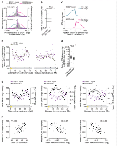
Figure 4. Factors influencing DSB processing. (A) Spatial correlation of SSDS coverage (data from Citationref. 21) with methylated nucleosomes. Each panel shows the mean of locally normalized profiles across the 20% of hotspots with the most asymmetric H3K4me3 patterns (left > right in top panel; right > left in bottom panel). The same local normalization factor was applied to Watson and Crick SSDS reads for each hotspot so that signal strengths on Watson and Crick were comparable. (B) Ratio of sum of locally normalized SSDS coverage in 3,001-bp windows around the centers of the subsets of hotspots from panel A. The ratios are plotted on a log2 scale but labeled according to a linear scale. The horizontal solid and dashed lines show the mean and 95% CI, respectively, estimated by bootstrap resampling from all hotspots without regard to H3K4me3 (a)symmetry. The bootstrap mean of 0.98 (-0.022 on log2 scale) is explained by the fact that the sum of locally normalized SSDS coverage of all hotspots is slightly lower on the Watson strand than on the Crick strand (Watson:Crick ratio of all hotspots is 0.98). (C) SSDS signal spreads for similar total distance toward high- and low-H3K4me3 sides. Each panel shows the mean of locally normalized profiles on Watson (top) and Crick (bottom) strands in the hotspots subsetted by H3K4me3 asymmetry. Local normalization was applied separately to Watson and Crick reads so that signal strengths were comparable between the subsets. Note that the curves match well at longer distances (≥ 800 bp from hotspot centers), suggesting that similar lengths of ssDNA are revealed regardless of H3K4me3 (a) symmetry. (D) SPO11 oligos and SSDS coverage display similar density patterns in centromere-proximal regions (left) but not in centromere-distal regions (right). Points are densities of SPO11 oligos (reads per million (RPM) per Mb) and SSDS tag counts (tags per million (TPM) per Mb), within coordinates defined by SSDS hotspots, in 1-Mb windows, averaged across all 19 autosomes. (E) SPO11-oligo density and either GC content (left panel) or heterochromatin marks H3K9me2/3 (center and right panels) in 1-Mb windows across centromere-proximal regions of all autosomes. The SPO11-oligo density data are reproduced from panel D to aid comparison. (F) Correlation between SPO11-oligo density and either GC content (left panel) or heterochromatin marks H3K9me2/3 (center and right panels) in 1-Mb windows across centromere-proximal regions, averaged across all autosomes. (G) Ratios of SSDS tag counts to SPO11-oligo read counts in SSDS hotspots differ between autosomal sub-chromosomal domains. “Sub-telomeric” is defined as the centromere-distal 5 Mb of each autosome. “Interstitial” is all other autosomal regions. One tag count and one SPO11-oligo read count were added to each hotspot. Boxplot outliers are not shown. P value is from Wilcoxon rank sum test.

Figure 5. Crossover asymmetry in hotspots with polymorphisms in putative PRDM9 binding sites. (A) Model for crossover asymmetry. A sequence polymorphism in a PRDM9 binding site may affect relative DSB frequencies on the 2 hotspot alleles, manifested as asymmetry in the locations of crossover breakpoints. If DSBs are preferentially formed on the B6 chromosome of a B6 × DBA hybrid mouse, crossover breakpoints will tend to lie to the left of the hotspot center when recombinant products are assayed after PCR amplification in the B6-to-DBA orientation, and will tend to lie to the right when amplified in the DBA-to-B6 orientation. (B and C) Examples of crossover hotspots with (B) or without (C) crossover asymmetry. (i) B6 (top) and DBA (bottom) sequences of putative 36-bp binding sites for PRDM9B6 at hotspot centers. The nucleotides shaded in yellow in HS59.5 highlight a polymorphism between the B6 and DBA haplotypes. In HS61.1, the PRDM9 motif shown is on the Crick strand. (ii) SPO11-oligo maps. Red lines indicate SPO11-oligo hotspots. (iii) Crossover breakpoints (densities expressed as centiMorgans (cM) per Mb) mapped by allele-specific PCR on sperm DNA in the B6-to-DBA (top) and DBA-to-B6 (bottom) orientation.Citation102,Citation103 Ticks represent tested polymorphisms. (iv) Cumulative distributions of crossover breakpoints with fitted Gaussian curves. The number indicates the distance between the 2 curves at the midpoint for each cumulative plot. Vertical dashed lines indicate hotspot centers. For hotspot HS61.1, zero values in both orientations at outlier position -1130 bp are not shown. (D) Crossover asymmetry is associated with presence of polymorphisms in putative PRDM9 binding sites at hotspots (Table S3). Crossover asymmetry was defined for each locus as the absolute difference between the midpoints of cumulative crossover breakpoint maps in the 2 orientations.
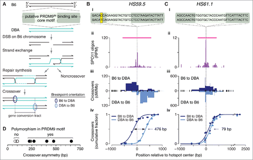
Figure 5. Crossover asymmetry in hotspots with polymorphisms in putative PRDM9 binding sites. (A) Model for crossover asymmetry. A sequence polymorphism in a PRDM9 binding site may affect relative DSB frequencies on the 2 hotspot alleles, manifested as asymmetry in the locations of crossover breakpoints. If DSBs are preferentially formed on the B6 chromosome of a B6 × DBA hybrid mouse, crossover breakpoints will tend to lie to the left of the hotspot center when recombinant products are assayed after PCR amplification in the B6-to-DBA orientation, and will tend to lie to the right when amplified in the DBA-to-B6 orientation. (B and C) Examples of crossover hotspots with (B) or without (C) crossover asymmetry. (i) B6 (top) and DBA (bottom) sequences of putative 36-bp binding sites for PRDM9B6 at hotspot centers. The nucleotides shaded in yellow in HS59.5 highlight a polymorphism between the B6 and DBA haplotypes. In HS61.1, the PRDM9 motif shown is on the Crick strand. (ii) SPO11-oligo maps. Red lines indicate SPO11-oligo hotspots. (iii) Crossover breakpoints (densities expressed as centiMorgans (cM) per Mb) mapped by allele-specific PCR on sperm DNA in the B6-to-DBA (top) and DBA-to-B6 (bottom) orientation.Citation102,Citation103 Ticks represent tested polymorphisms. (iv) Cumulative distributions of crossover breakpoints with fitted Gaussian curves. The number indicates the distance between the 2 curves at the midpoint for each cumulative plot. Vertical dashed lines indicate hotspot centers. For hotspot HS61.1, zero values in both orientations at outlier position -1130 bp are not shown. (D) Crossover asymmetry is associated with presence of polymorphisms in putative PRDM9 binding sites at hotspots (Table S3). Crossover asymmetry was defined for each locus as the absolute difference between the midpoints of cumulative crossover breakpoint maps in the 2 orientations.
Supplemental material

KCCY_S_1361065.zip

Download Zip (335.6 KB)