
Figures & data
Figure 1. Chromosomal changes that take place during meiosis. Diagram illustrating the major steps in meiosis. Meiosis proceeds through a single cycle of DNA replication followed by two cycles of cell division, resulting in a reduction in chromosome copy number to yield haploid spores or gametes. We refer the reader to several recent reviews for more in–depth descriptions of the mechanisms underlying meiosis [Citation1,Citation3,Citation33].
![Figure 1. Chromosomal changes that take place during meiosis. Diagram illustrating the major steps in meiosis. Meiosis proceeds through a single cycle of DNA replication followed by two cycles of cell division, resulting in a reduction in chromosome copy number to yield haploid spores or gametes. We refer the reader to several recent reviews for more in–depth descriptions of the mechanisms underlying meiosis [Citation1,Citation3,Citation33].](/cms/asset/0c87ea6b-cd0d-4b67-b916-785e60ed142f/kccy_a_1553355_f0001_oc.jpg)
Figure 2. Simplified overview of homologous recombination. (a) Diagram depicting the formation of a DSB followed by end processing of the break to yield long 3’ssDNA overhangs. The ssDNA can be paired with a homologous dsDNA (shown in red) to yield a metastable D–loop intermediate. The 3ʹend of the invading strand of the D–loop can then be used to prime DNA synthesis, which yields a more stable single end invasion product (SEI). (b) The SEI can then channeled through the synthesis–dependent strand annealing pathway. In this case, the SEI product is displaced from the homologous template and can repair with the second processed DNA end. Additional DNA synthesis followed by strand ligation yields noncrossover repair products. (c) Alternatively, the second end of the processed DNA can anneal to the homologous template, which can result in the formation of an interlinked double Holliday junction (dHJ) after DNA synthesis and strand ligation. The dHJ can be dissolved to yield noncrossover products, or it can undergo resolution through endonucleolytic cleavage, which can yield either noncrossover products (not depicted) or crossover products.
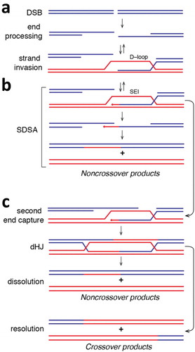
Figure 3. Spatial organization of protein components within the meiotic presynaptic complex. (a) Diagram illustrating the “alternate end” and “mixed filament” models describing the organization of the Rad51 and Dmc1 recombinases at the processed DSBs formed through the endonuclease active of Spo11 during meiosis. Each model invokes the formation of homotypic Rad51 and Dmc1 filaments (as depicted) and current research favors the “mixed filament” model [Citation11,Citation43]. (b) Cartoon model depicting the hypothetical spatial organization of recombination accessory factors based upon their binding interactions with the Rad51 or Dmc1 and the mixed filament model for meiotic presynaptic complex. The locations of some of the factors remains unknown, and a more detailed understanding of the protein binding mechanisms and protein distributions remains an active area of investigation. See main text for additional details.
![Figure 3. Spatial organization of protein components within the meiotic presynaptic complex. (a) Diagram illustrating the “alternate end” and “mixed filament” models describing the organization of the Rad51 and Dmc1 recombinases at the processed DSBs formed through the endonuclease active of Spo11 during meiosis. Each model invokes the formation of homotypic Rad51 and Dmc1 filaments (as depicted) and current research favors the “mixed filament” model [Citation11,Citation43]. (b) Cartoon model depicting the hypothetical spatial organization of recombination accessory factors based upon their binding interactions with the Rad51 or Dmc1 and the mixed filament model for meiotic presynaptic complex. The locations of some of the factors remains unknown, and a more detailed understanding of the protein binding mechanisms and protein distributions remains an active area of investigation. See main text for additional details.](/cms/asset/6b5a26b0-827e-446a-864a-e2b81100e0f1/kccy_a_1553355_f0003_oc.jpg)