1,636
Views
3
CrossRef citations to date
0
Altmetric
Original Articles

Modeling of Material Orientation Effects on AHSS Crush and Fracture Behavior in Axial Crush Tests

, , &
Pages S23-S29 | Received 07 Mar 2013, Accepted 25 Mar 2013, Published online: 01 Aug 2013

Figures & data

Fig. 1 Geometry of the 12-sided design (color figure available online).

Fig. 1 Geometry of the 12-sided design (color figure available online).

Table 1 Steel grades and material properties in L and T directions.

Fig. 2 Comparisons of crack length (color figure available online).

Fig. 2 Comparisons of crack length (color figure available online).

Table 2 Comparison of crush load and crush distance

Fig. 3 Measured force–displacement curves for DP780 (color figure available online).

Fig. 3 Measured force–displacement curves for DP780 (color figure available online).

Fig. 4 Comparisons of tested deformation modes for DP780 (color figure available online).

Fig. 4 Comparisons of tested deformation modes for DP780 (color figure available online).

Fig. 5 Optimization of the extension of stress–strain curve in the transverse direction (color figure available online).
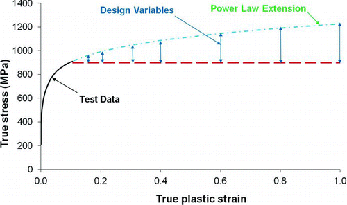
Fig. 5 Optimization of the extension of stress–strain curve in the transverse direction (color figure available online).

Fig. 6 Load curves from uniaxial tension tests on DP780 in the transverse direction (color figure available online).
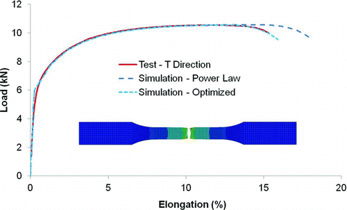
Fig. 6 Load curves from uniaxial tension tests on DP780 in the transverse direction (color figure available online).

Fig. 7 Optimized extension of the stress–strain curve for DP780 in the transverse direction (color figure available online).
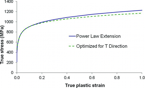
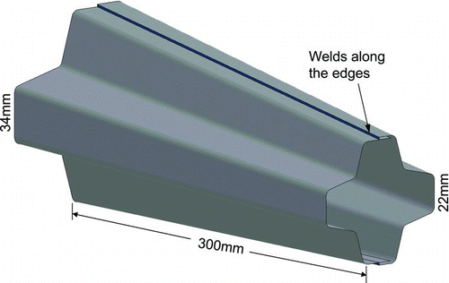
Fig. 7 Optimized extension of the stress–strain curve for DP780 in the transverse direction (color figure available online).
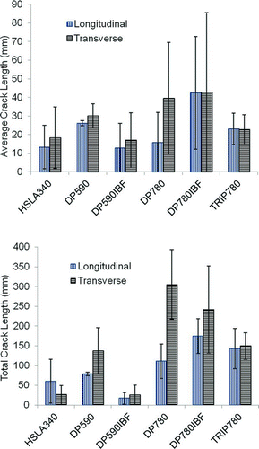
Fig. 8 Estimated fracture locus for DP780 (color figure available online).

Fig. 8 Estimated fracture locus for DP780 (color figure available online).

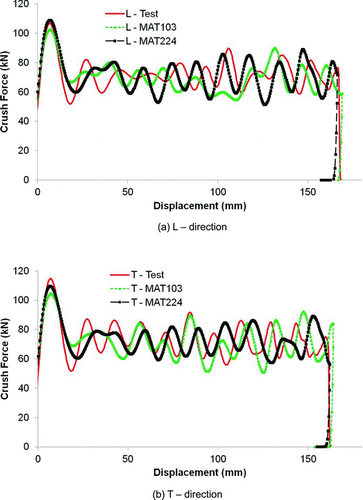
Fig. 9 Comparison of predicted force–displacement curves for DP780: (a) L direction and (b) T direction (color figure available online).
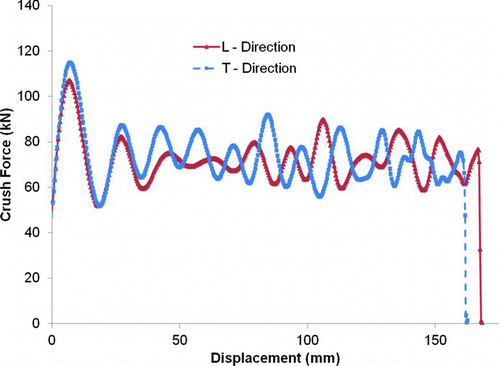
Fig. 9 Comparison of predicted force–displacement curves for DP780: (a) L direction and (b) T direction (color figure available online).
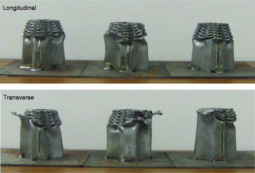
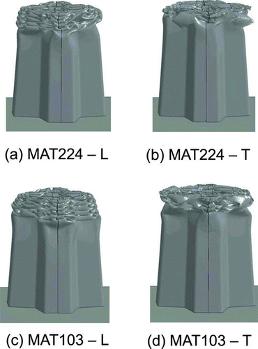
Fig. 10 Comparison of predicted deformation modes for DP780: (a) MAT224, L direction, (b) MAT224, T direction, (c) MAT103, L direction, and (d) MAT103, T direction (color figure available online).
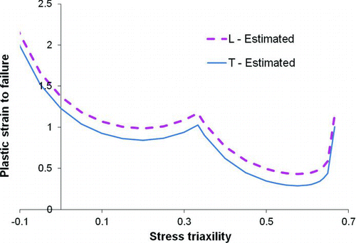
Fig. 10 Comparison of predicted deformation modes for DP780: (a) MAT224, L direction, (b) MAT224, T direction, (c) MAT103, L direction, and (d) MAT103, T direction (color figure available online).