2,680
Views
2
CrossRef citations to date
0
Altmetric
Original Articles

Methodology for Using Advanced Event Data Recorders to Reconstruct Vehicle Trajectories for Use in Safety Impact Methodologies (SIM)

, &
Pages S77-S86 | Received 15 Mar 2013, Accepted 12 Apr 2013, Published online: 01 Aug 2013

Figures & data

Fig. 1 SIM framework developed by the NHTSA (Carter et al. Citation2009; Funke et al. Citation2011).
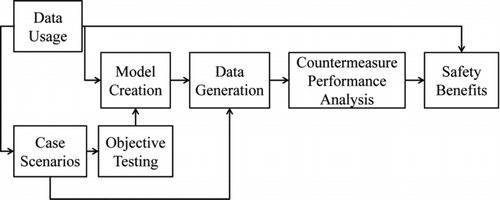
Fig. 1 SIM framework developed by the NHTSA (Carter et al. Citation2009; Funke et al. Citation2011).

Fig. 2 Scene diagram and scene and vehicle photographs prepared by crash investigator in NASS/CDS case 2011-11-148 (color figure available online).
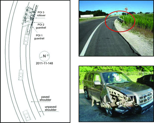
Fig. 2 Scene diagram and scene and vehicle photographs prepared by crash investigator in NASS/CDS case 2011-11-148 (color figure available online).

Fig. 3 Precrash vehicle speed, accelerator pedal, and brake switch status for NASS/CDS case 2011-11-148 (color figure available online).
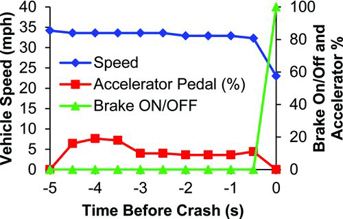
Fig. 3 Precrash vehicle speed, accelerator pedal, and brake switch status for NASS/CDS case 2011-11-148 (color figure available online).

Fig. 4 Steering wheel angle of vehicle in NASS/CDS case 2011-11-148 (color figure available online).
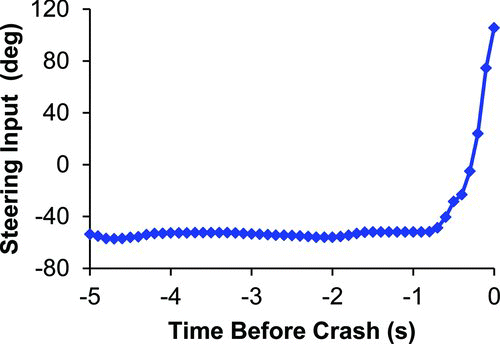
Fig. 4 Steering wheel angle of vehicle in NASS/CDS case 2011-11-148 (color figure available online).

Fig. 5 Process for simulating and validating vehicle trajectory models using advanced EDR data (color figure available online).
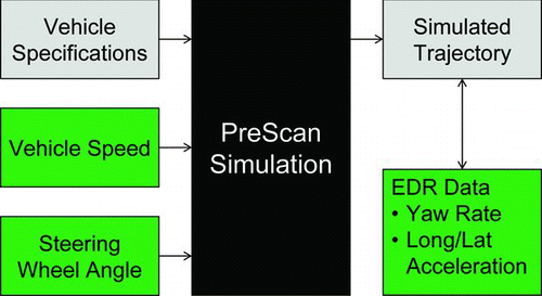
Fig. 5 Process for simulating and validating vehicle trajectory models using advanced EDR data (color figure available online).

Table 1 Vehicle model parameters for Ford vehicles

Table 2 Crash type, off-road travel, and ESC/ABS activation in advanced EDR cases

Fig. 6 Precrash speed, accelerator pedal, and brake switch for case 2011-11-148 (color figure available online).
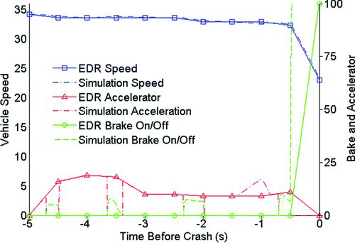
Fig. 6 Precrash speed, accelerator pedal, and brake switch for case 2011-11-148 (color figure available online).

Fig. 7 Precrash yaw rate for EDR and simulation for case 2011-11-148 (color figure available online).
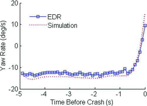
Fig. 7 Precrash yaw rate for EDR and simulation for case 2011-11-148 (color figure available online).

Fig. 8 Steering wheel angle for case 2011-11-149 (color figure available online).

Fig. 8 Steering wheel angle for case 2011-11-149 (color figure available online).

Fig. 9 Precrash yaw rate for EDR and simulation for case 2011-11-149 (color figure available online).
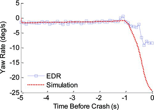
Fig. 9 Precrash yaw rate for EDR and simulation for case 2011-11-149 (color figure available online).

Table 3 Average absolute error in maximum yaw rate in simulations compared to EDR

Fig. 10 EDR recorded and simulation yaw rate for case 2011-11-149 with modified friction (color figure available online).
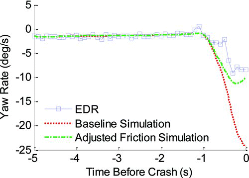
Fig. 10 EDR recorded and simulation yaw rate for case 2011-11-149 with modified friction (color figure available online).

Fig. 11 Scene reconstruction for case 2011-11-148 (color figure available online).

Fig. 11 Scene reconstruction for case 2011-11-148 (color figure available online).

Fig. 12 Trajectory of right front wheel with and without LDW for case 2011-11-148 (color figure available online).
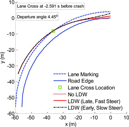
Fig. 12 Trajectory of right front wheel with and without LDW for case 2011-11-148 (color figure available online).

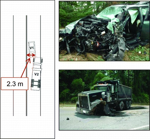
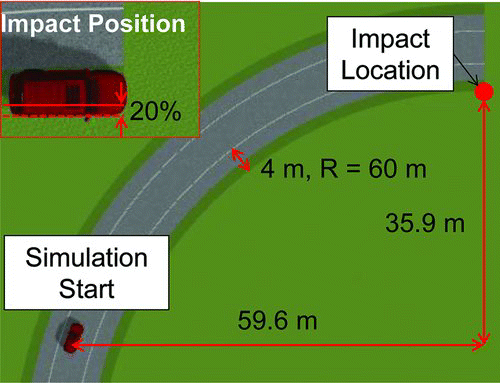
Fig. 13 Scene diagram and vehicle damage in case 2011-48-111 (color figure available online).

Fig. 13 Scene diagram and vehicle damage in case 2011-48-111 (color figure available online).

Fig. 14 Vehicle initial position given final impact angles for case 2011-48-111 (color figure available online).
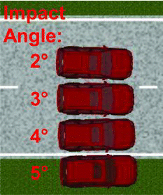
Fig. 14 Vehicle initial position given final impact angles for case 2011-48-111 (color figure available online).

Fig. 15 Trajectory of left front wheel with and without LDW for case 2011-48-111 (color figure available online).
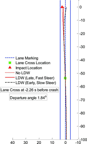
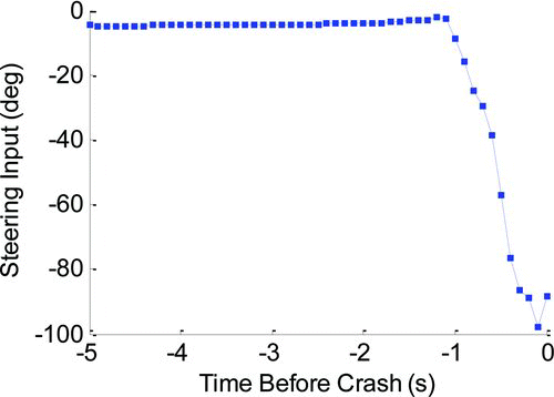
Fig. 15 Trajectory of left front wheel with and without LDW for case 2011-48-111 (color figure available online).
Supplemental material