1,992
Views
18
CrossRef citations to date
0
Altmetric
Original Articles

An Open Simulation Approach to Identify Chances and Limitations for Vulnerable Road User (VRU) Active Safety

, , &
Pages S2-S12 | Received 27 Feb 2013, Accepted 16 Apr 2013, Published online: 01 Aug 2013

Figures & data

Fig. 1 Concept for a simulation model.

Fig. 1 Concept for a simulation model.

Fig. 2 Impact location for near-side pedestrians running from behind an obstruction (color figure available online).
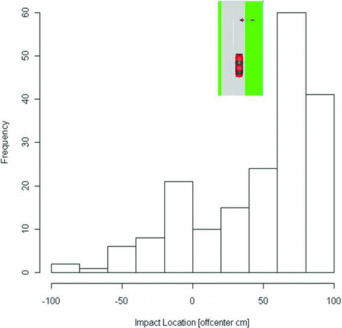
Fig. 2 Impact location for near-side pedestrians running from behind an obstruction (color figure available online).

Fig. 3 Driving speed and impact location for obscured and running near-side and far-side pedestrians (color figure available online).
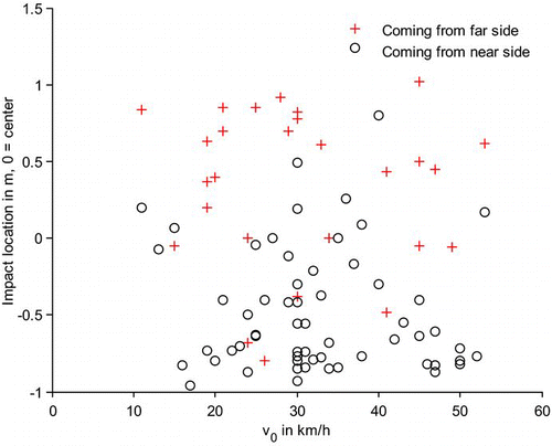
Fig. 3 Driving speed and impact location for obscured and running near-side and far-side pedestrians (color figure available online).

Fig. 4 Accident scenario parameters. Near side/far side shown for driving on the right side

Fig. 4 Accident scenario parameters. Near side/far side shown for driving on the right side

Fig. 5 Shark's fin curve for static pedestrian at 50 percent position. The maximum speed reduction is 38 km/h, which is also the maximum avoidance speed.
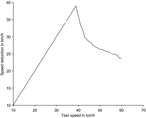
Fig. 5 Shark's fin curve for static pedestrian at 50 percent position. The maximum speed reduction is 38 km/h, which is also the maximum avoidance speed.

Table 1 Overview of system parameters

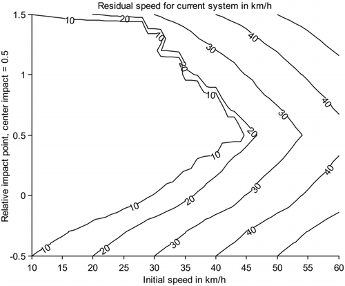
Fig. 6 Contour plot of residual speeds = f(impact point, test speed) for scenario “child running (8 km/h) from behind an obstruction (1 m from vehicle path)” for current, future, and physical limits AEB systems (from left to right). Impact point 0 refers to near side, impact point 1 to far side with respect to the pedestrian's origin. Upper row: system intervenes as soon as accident becomes unavoidable (max lateral acceleration = 1 g). Middle row, 0.6 g, lower row: 0 g (steering intervention not taken into account). All system parameters are summarized in . Note that because the distance to the obstruction and all speeds are constant, higher impact point values mean that the pedestrian had more time to travel, thus the initial visibility TTC was earlier. High impact point values = high initial TTCs; low impact point values = low initial TTCs. All values only valid for high friction (μ = 1).
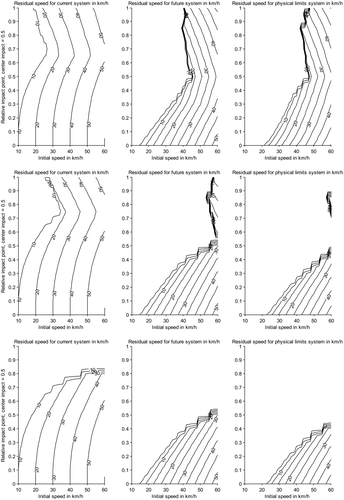
Fig. 6 Contour plot of residual speeds = f(impact point, test speed) for scenario “child running (8 km/h) from behind an obstruction (1 m from vehicle path)” for current, future, and physical limits AEB systems (from left to right). Impact point 0 refers to near side, impact point 1 to far side with respect to the pedestrian's origin. Upper row: system intervenes as soon as accident becomes unavoidable (max lateral acceleration = 1 g). Middle row, 0.6 g, lower row: 0 g (steering intervention not taken into account). All system parameters are summarized in Table 1. Note that because the distance to the obstruction and all speeds are constant, higher impact point values mean that the pedestrian had more time to travel, thus the initial visibility TTC was earlier. High impact point values = high initial TTCs; low impact point values = low initial TTCs. All values only valid for high friction (μ = 1).

Fig. 7 Contour plot of residual speeds for walking adult (5 km/h) without obstruction, current AEB system, future system, physical limit system, from left to right. Relative impact position ranges from 0 (near side corner of vehicle) to 1 (far side corner of vehicle). Maximum lateral acceleration is 1 g (upper row), ignored (lower). Ignoring the steering-avoidance criterion means that braking should start, for example, as soon as the pedestrian is almost in the path, cannot stop anymore, and vehicle and pedestrian will collide if braking is not applied.
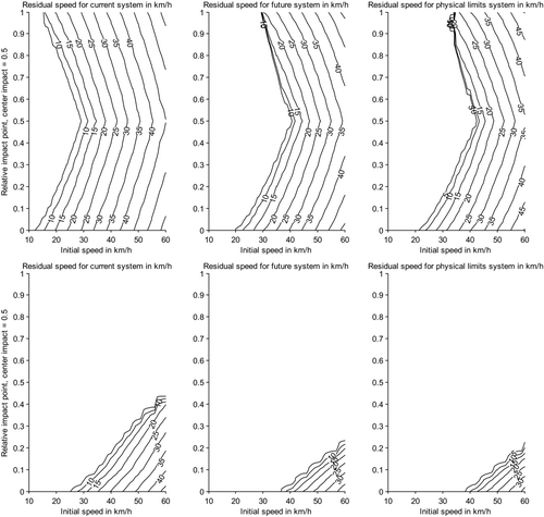
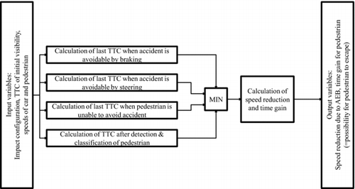
Fig. 7 Contour plot of residual speeds for walking adult (5 km/h) without obstruction, current AEB system, future system, physical limit system, from left to right. Relative impact position ranges from 0 (near side corner of vehicle) to 1 (far side corner of vehicle). Maximum lateral acceleration is 1 g (upper row), ignored (lower). Ignoring the steering-avoidance criterion means that braking should start, for example, as soon as the pedestrian is almost in the path, cannot stop anymore, and vehicle and pedestrian will collide if braking is not applied.
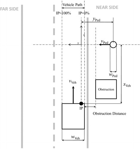
Fig. 8 Residual speeds for a simple set of bicycle parameters.

Fig. 8 Residual speeds for a simple set of bicycle parameters.