2,073
Views
4
CrossRef citations to date
0
Altmetric
Original Articles

Bumper and Grille Airbags Concept for Enhanced Vehicle Compatibility in Side Impact: Phase II

, &
Pages S30-S39 | Received 12 Mar 2013, Accepted 02 Jun 2013, Published online: 01 Aug 2013

Figures & data

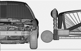
Fig. 1 FE model for via sled simulation.

Fig. 1 FE model for via sled simulation.

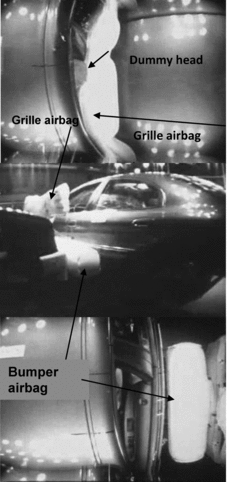
Fig. 2 External airbags interaction with vehicle structure and crash dummy.

Fig. 2 External airbags interaction with vehicle structure and crash dummy.

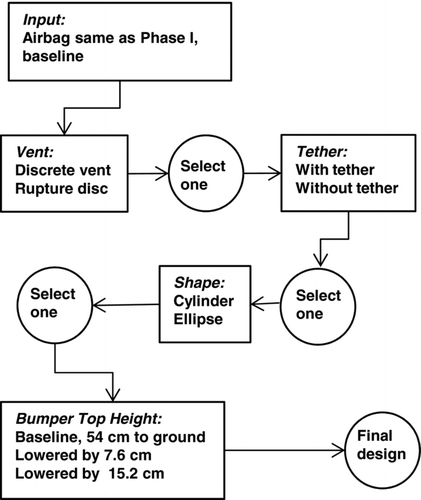
Fig. 3 Flow chart for bumper airbag design parameters iterations.

Fig. 3 Flow chart for bumper airbag design parameters iterations.

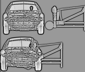
Fig. 4 FE Model of the SUV-Type buck-to-passenger car side impact.

Fig. 4 FE Model of the SUV-Type buck-to-passenger car side impact.

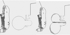
Fig. 5 Circular cylinder bumper airbag with/without tether (airbag center section).

Fig. 5 Circular cylinder bumper airbag with/without tether (airbag center section).

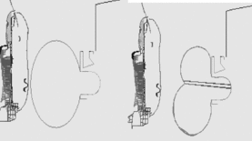
Fig. 6 Elliptical cylinder bumper airbag with/without tether (airbag center section).

Fig. 6 Elliptical cylinder bumper airbag with/without tether (airbag center section).

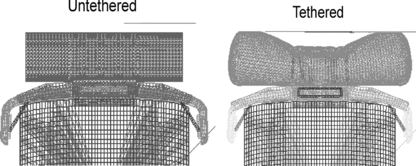
Fig. 7 Top view of the airbags with and without tether.

Fig. 7 Top view of the airbags with and without tether.

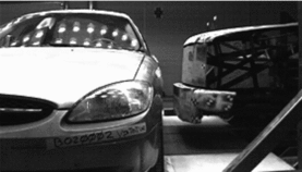
Fig. 8 Via sled side impact test set-up.

Fig. 8 Via sled side impact test set-up.

Fig. 9 Via sled side impact test set-up.

Fig. 9 Via sled side impact test set-up.

Table 1 Tether effect on normalized dummy responses

Table 2 Bumper airbag shape effect on normalized dummy responses

Table 3 Bumper height effect on normalized dummy responses

Table 4 Via sled test results and airbags characteristics

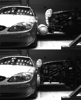
Fig. 10 Via sled side impact test with SUV-type buck equipped with external airbags.

Fig. 10 Via sled side impact test with SUV-type buck equipped with external airbags.

Table 5 Door armrest velocity obtained from the Via sled tests

Table 6 Finite element results for reaction surface gauge optimization

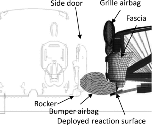
Fig. 11 External airbags finite element concept model with reaction surface.

Fig. 11 External airbags finite element concept model with reaction surface.

Fig. 12 Simulation of external airbag finite element concept model with reaction.

Fig. 12 Simulation of external airbag finite element concept model with reaction.

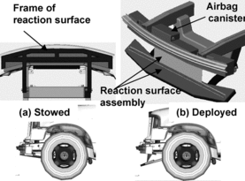
Fig. 13 Bumper airbag reaction surface hardware and assembly.

Fig. 13 Bumper airbag reaction surface hardware and assembly.

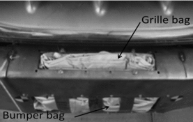
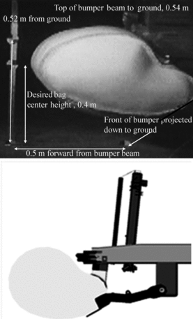
Fig. 14 Prototype bumper airbag final shape mounted on an SUV.

Fig. 14 Prototype bumper airbag final shape mounted on an SUV.

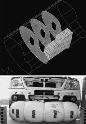
Fig. 15 Pre-inflated chambered prototype bumper airbag concept with bulkheads.

Fig. 15 Pre-inflated chambered prototype bumper airbag concept with bulkheads.

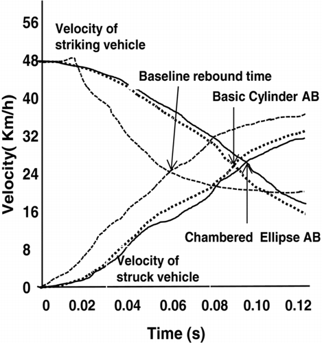
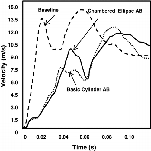
Fig. 16 Target and bullet velocity-time histories from the Via sled tests.

Fig. 16 Target and bullet velocity-time histories from the Via sled tests.

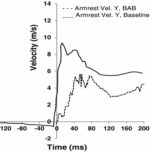
Fig. 17 Lateral velocity time-history curves of the armrest in the target vehicle.

Fig. 17 Lateral velocity time-history curves of the armrest in the target vehicle.

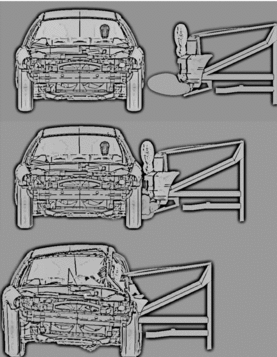
Fig. 18 Bumper and grille airbags deployment sequence in vehicle-to-vehicle test.

Fig. 18 Bumper and grille airbags deployment sequence in vehicle-to-vehicle test.

Fig. 19 Armrest velocity comparisons.

Fig. 19 Armrest velocity comparisons.

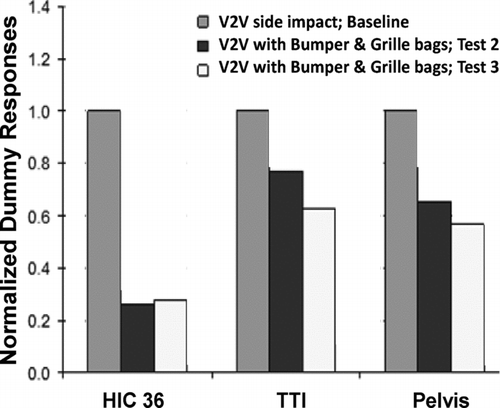
Fig. 20 Normalized dummy responses for target vehicle.

Fig. 20 Normalized dummy responses for target vehicle.