Figures & data
Figure 1. Picture showing the location of the center-mounted airbag
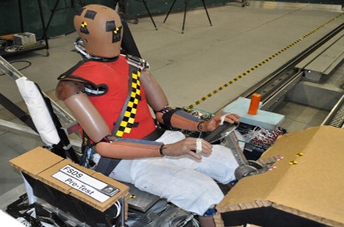
Figure 2. Calculation method for the SD deflections. A and B refer to the origin in the undeformed and deformed contours. The peak deflection is the difference between the vectors AA1 and BB1. Refer to the text for details.
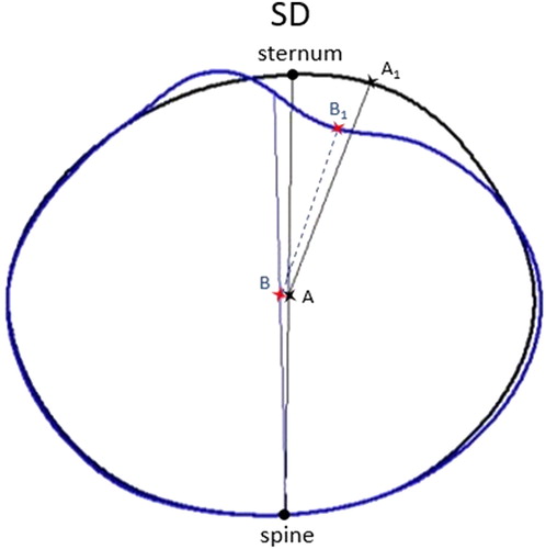
Figure 3. Calculation method for the ID deflections. A and B refer to the origin in the undeformed and deformed contours. The peak deflection is the difference between the vectors AA1 and BB1. Refer to the text for details.
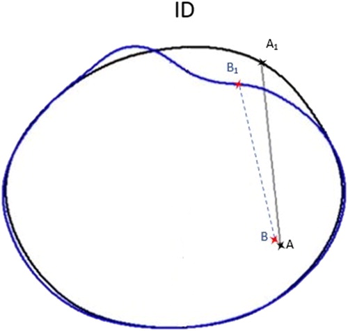
Figure 4. Calculation method for the TD deflections. A and B refer to the origin in the undeformed and deformed contours. The peak deflection is the difference between the vectors AA1 and BB1. Refer to the text for details.

Figure 5. Peak chest deflections at the upper thorax level.
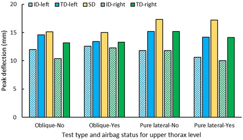
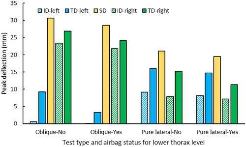
Figure 6. Peak chest deflections at the lower thorax level.