
Figures & data
Figure 1. Rear bumper beam deformation diagram.
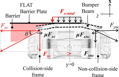
Figure 2. Schematic diagram of bow-shaped rear bumper beam structure.
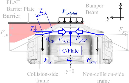
Figure 3. Set up for drop test of rear component.
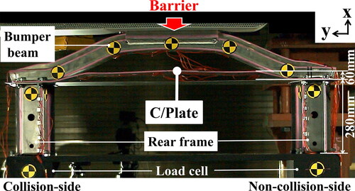
Figure 4. Fyc Comparison with and without C/Plate.
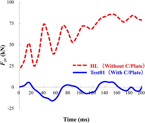
Figure 5. Timing of increase in Fx-total, Fyc, and C/Plate strain for Test02.
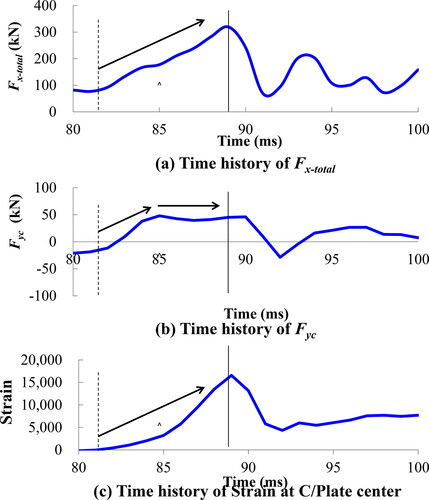
Figure 6. Photograph of rear component Test02 after drop test.
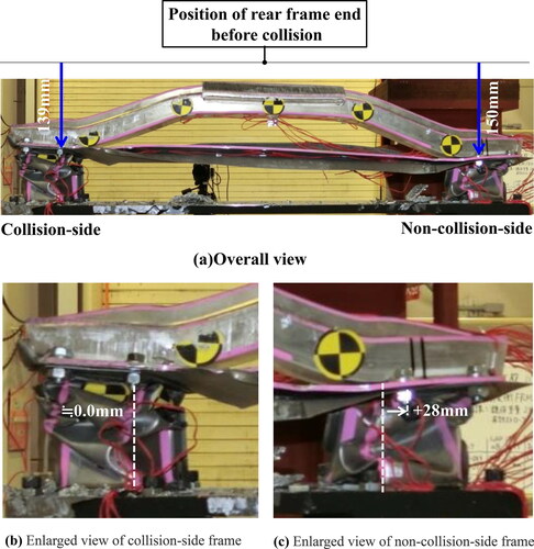
Figure 7. Comparison of energy absorption.
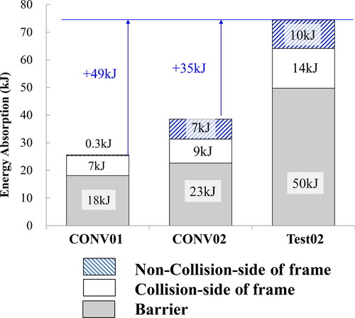
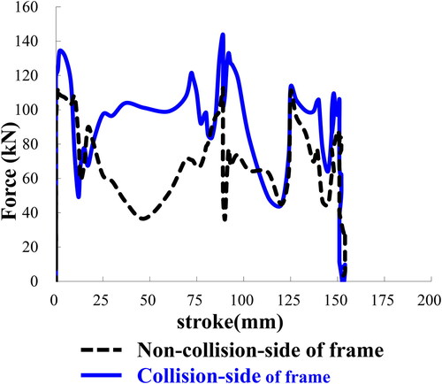
Figure 8. Comparison of load-stroke curves of collision and non-collision-side frames.
(The deformation on the two frames was assumed to be the same as on the non-collision side.)
Supplemental material