
Figures & data
Figure 1. Study overview and the generation of baseline male and female SAFER pedestrian HBMs: The occupant HBM was computationally positioned to an upright standing position by using pulling cables. The upright HBM was subsequently morphed to obtain the body shape and skeleton geometry representative of a 50th percentile male and female, constituting the newly established baseline pedestrian versions of the SAFER HBM. To evaluate the pedestrian HBMs and personalization technique, the male pedestrian HBM was morphed according to personalized anthropometries of 3 male PMHSs struck laterally using a generic buck model.
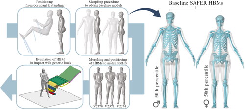
Figure 2. Illustrations of a selection of the positioning steps to obtain an upright SAFER HBM.
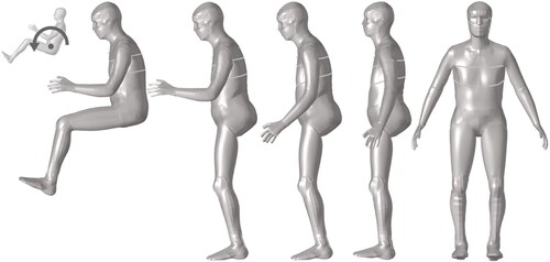
Figure 3. Basic morphing framework using a target geometry and template HBM. (i) The target and template outer skin and skeleton are voxelized to segmented images and rigidly aligned by the head. (ii) Demons registration using the template image set as the fixed image and the target image set as moving image to generate a displacement field defined on the fixed image space. (iii) The displacement field is applied to the template HBM, morphing the HBM to the desired personalized HBM. (iv) The image of the template HBM is hardened by the inverse of the generated displacement field and is subsequently compared with the target image set to quantify personalization accuracy using Dice and HD95 metrics.
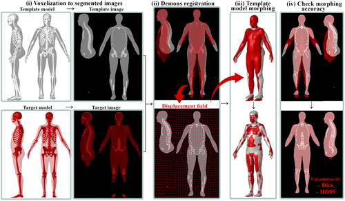
Table 1. Anthropometric details and measurements of the positioned HBMs.
Table 2. Minimum Jacobians, Dice values, and HD95 distances for the baseline HBMs and personalized HBMs (PMHSs).
Figure 4. Model-to-model absolute distance between the target geometry and personalized pedestrian HBMs of the female outer skin and skeleton (left) and male outer skin and skeleton (right). Red indicates a larger absolute error, and blue shows a perfect overlap.
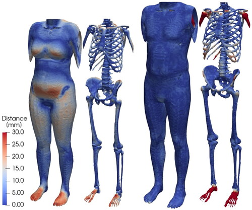
Figure 5. Trajectories of the personalized HBMs in lateral impacts: Subject V2370 (top), subject V2371 (middle), and subject V2374 (bottom). Markers are displayed for every 30 ms from the point of leg contact (t = 0).
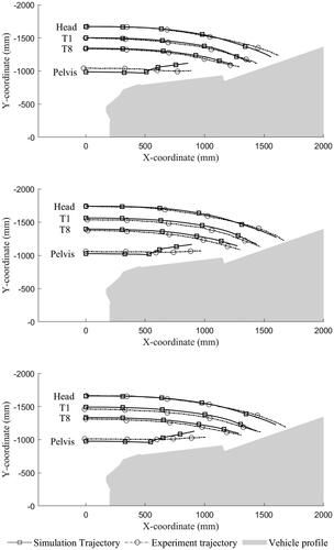
Figure 6. Posterior view of V2374 in selected time steps. Images of PMHS experiments are taken from a previous publication by Wu et al. (Citation2017).
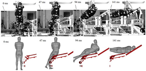
Table 3. Head contact times, WADs, and simulated strain in the skull bone.
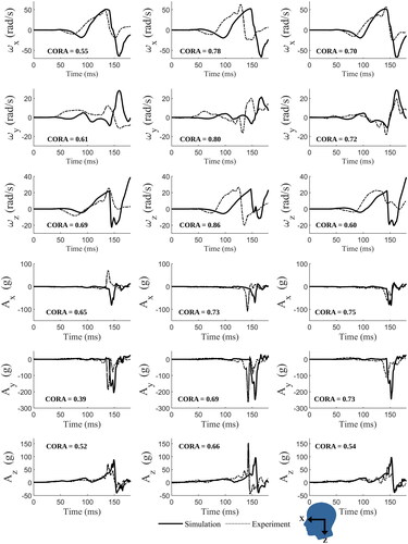
Figure 7. Component head CoG acceleration A and angular velocity ω time histories for subject V2370 (left column), subject V2371 (middle column), and subject V2374 (right column).
Supplemental Material
Download Zip (2.2 MB)Data availability statement
All data relevant to the study are included in the article or uploaded as supplementary information.