
Figures & data
Figure 1. MFCS topology.
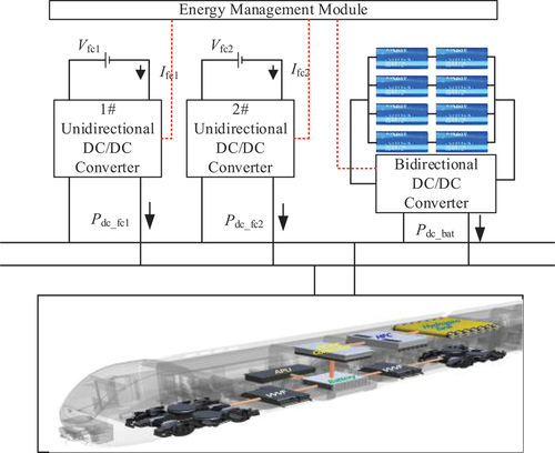
Figure 2. Fuel cell polarization curve.
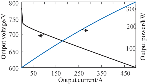
Table 1. Fuel cell parameters.
Figure 3. Relationship between battery open circuit voltage and SOC.
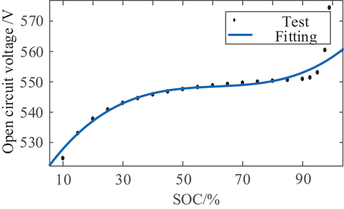
Figure 4. Hierarchical energy management strategy in consideration of fuel cell degradation.
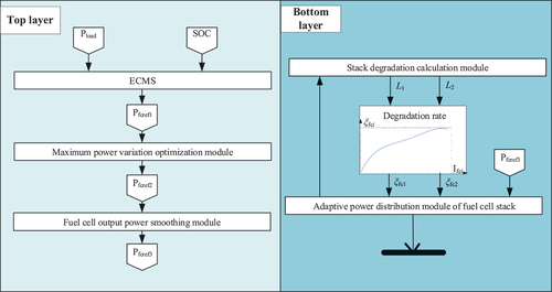
Figure 5. Power distribution of the hybrid system.
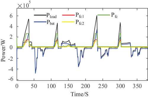
Figure 6. Comparison of the standard deviation of power.
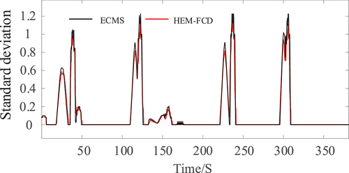
Figure 7. Degree of MFCS degradation under the three methods.
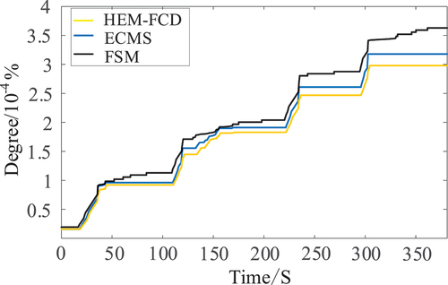
Figure 8. Fuel cell operating pressure. (a) 1# fuel cell operating pressure based on FSM, (b) 1 # fuel cell operating pressure based on ECMS, (c) 1# fuel cell operating pressure based on HEM-FCD, (d) 2# fuel cell operating pressure based on HEM-FCD.
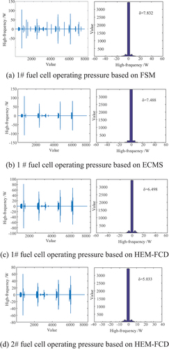
Figure 9. Comparison of equivalent hydrogen consumption.
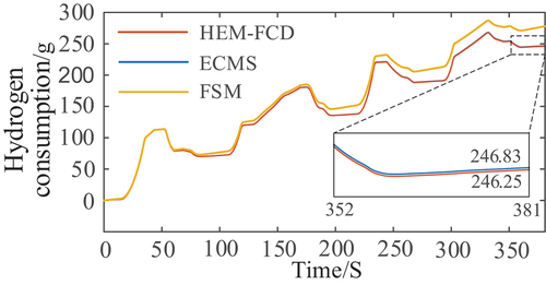
Figure 10. Comparison of SOC variation curve.
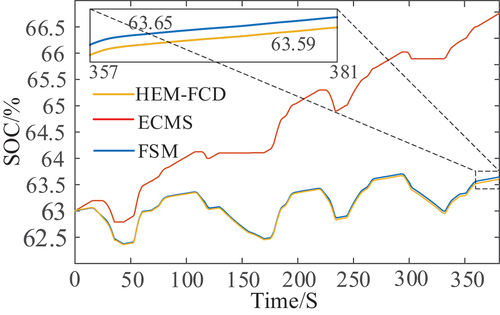
Table 2. Fuel cell parameters.