Figures & data
Table 1. Printing parameters for FDM-printed 3D graphene strain sensor.
Figure 1. (a) schematic of FDM-printed graphene strain sensor. 3D modeling of dog-bone-shaped strain sensor with parallel (b) and zigzag (c) direction of filament deposition. FDM-based graphene strain sensor printed, with microscope images for parallel (b1 and b2) and zigzag-patterned strain sensors (c1 and c2).
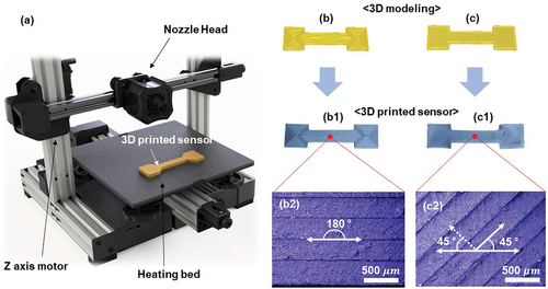
Figure 2. (a) I – V curves of the printed sensors for 45° and 180° patterns at a varying voltage gradient from 0 to 1 V. (b) sensing performance of the composite strain sensor under tension with applied strains ranging from 0.05% to 0.25%. (c) sensitivity of the sensors calculated through regression analysis. (d) calculation of gauge factor for 45° and 180° patterns. (e) response of the 45° and 180° patterns to equivalent lateral forces with different pressures for two times.
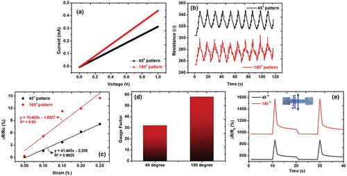
Figure 3. (a) response force to a specific applied strain of 0.25%. CFD-based simulation of cracks within a rectangular solid under a tension force of (b) 0.1 and (c) 0.12 MPa. (d) response of the 45° and 180° patterns under the same tensile and compressive strains of 0.25% in five steps.
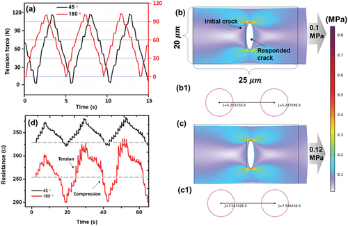
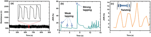
Figure 4. (a) fully recoverable electrical resistance without hysteresis at a 0.25% stretching rate for 1000 cycles. (b) sensitive responses of the 3D-printed graphene strain sensor for different tapping stresses. (c) sensing performance under twisting stresses.