
Figures & data
Figure 1. Local ventilation controls (A) High-Volume Evacuator (HVE), (B) ISOVAC Dental Isolator Adapter (ISO), and (C) Extraoral Suction Unit (EOS).
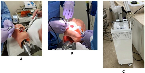
Figure 2. Room layout for Phase One, illustrating the centrally located procedure operatory (SidePak monitoring) and the neighboring four operatories (pDR monitoring).
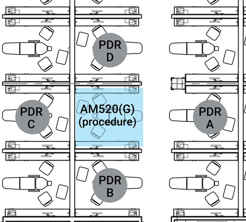
Table 1. Procedures and ventilation control devices evaluated in Phase One.
Figure 3. Clinic overview showing sampler deployment and room occupancy during Phase Two of the study.
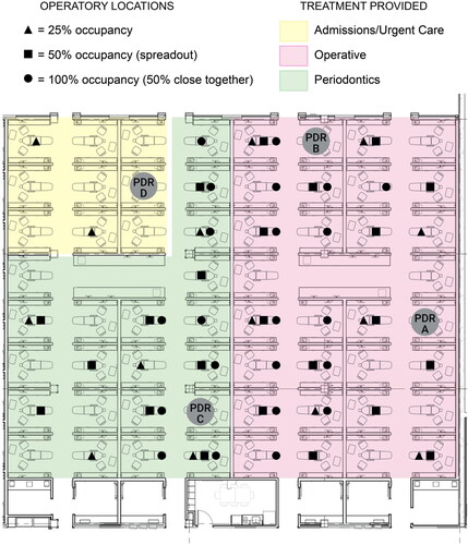
Table 2. Concentrations, in µg/m3 using SidePak AM520, and significance test results for concentrations measured near the dental assistant during simulated procedures, for the four local exhaust methods and four dental procedures.
Table 3. Summary of time-weighted average respirable aerosol concentration in areas adjacent to simulated dental procedures.
Table 4. Time-weighted averages of respirable aerosol concentrations (µg/m3), by occupancy, during Phase Two sampling, using pDRs.
Supplemental Material
Download PDF (376.8 KB)Data availability
Field data are available upon reasonable request to T. R. Anthony.