Figures & data
Figure 1. The collecting duct branches of the host kidney avoid contact with the eUB branches. (a–d) Show eUBs (marked with yellow asterisk) grafted in the MM of host kidneys where the CD of the host, facing the graft, stop expanding in A, B or tilt their branches (dotted lines in c, d) to avoid contact with the eUB graft branches. Scale bar = 100 µm.
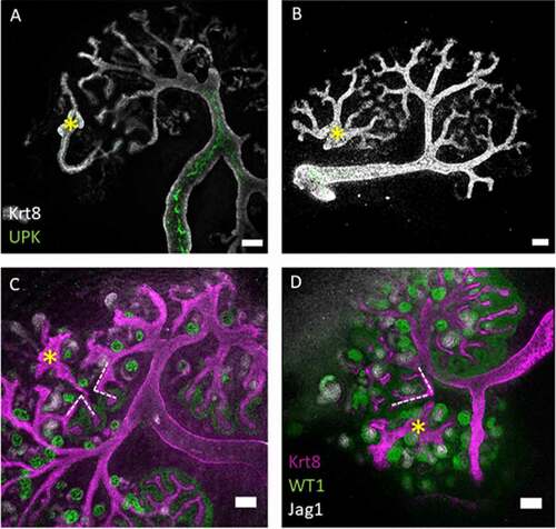
Figure 2. The eUB can be induced to connect to the collecting duct system of a natural kidney. (a) Steps of the process of eUB connection to host kidney CD. (b) Bright field image showing the GFP-eUB connected to the collecting duct tree and showing branching. (c) Immunofluorescence stain of the eUB (arrow), connected to the collecting duct tree and show no UPK expression. (d) Bright field image showing GFP-eUB connected to the collecting duct tree (arrow) and showing branching. (e) Immunofluorescence stain of D, showing eUB branched and induced nephron formation. (E’) Magnified image of E showing the connected eUB surrounded by WT1+ and Jag1+ nephrons. (CD; collecting duct, N; Nephron, PT; proximal tubule).
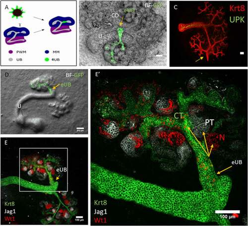
Figure 3. The eUB can be induced to connect to the ureter of a natural kidney. (a) Steps of the process of eUB connection to host kidney ureter. (b) Bright field image showing the GFP-eUB grafted and connected to the ureter (arrow) of a cultured kidney. (c) High-power immunofluorescence image of an eUB connected to the ureter, showing UPK expression, (arrow points to the graft, as in B). (d) Another grafted eUB connected to a host ureter. (e) Immunofluorescence stain of D showing Krt8, UPK and ASMA expression in the graft as well as the host. (E’) Isolated ASMA channel of E, showing smooth muscle coat around the connected graft as well as the ureter (E”) Individual UPK channel shows UPK expression in both the ureter and the connected graft. Scale bar = 100 µm.
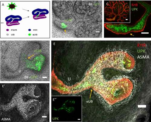
Figure 4. Contraction of the grafted eUB-derived ureter-like tissue and the natural ureter connected to it. (a) shows a starting frame of the video recording (video 3S); the graft which is connected to the host ureter can be identified by the GFP fluorescence, and the arrows indicate the places at which contractions in the graft and the nearby natural ureter were timed. (b) A graph shows the timings at which contractions occurred, shown as dots on the same time-scale.
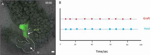
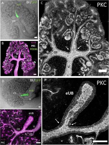
Figure 5. Connections between grafted eUBs and host CD/Ureter show open lumens. (a) Bright field image showing the GFP-eUB connected to the collecting duct system of a host kidney and showing branching. (b) The apical domain protein kinase C (PKC), and the epithelial marker Krt8 stain of the grafted kidney showing a connected lumen between the eUB graft and the collecting duct branches of the host kidney (arrow), early nephrons (expressing PODXL) can be seen connected to the graft. (c) Isolated channel of PKC, for clarity. (d) Bright field image of an GFP-eUB connected to the ureter of a cultured kidney, to show the position of the graft (e) The apical domain PKC and the epithelial marker Krt8 stain showing that the lumen is continuous between the graft and host tubules (arrows). (f) Shows the PKC channel only for clarity. (U: ureter, CD: collecting duct, eUB: engineered UB). Scale bar = 100 µm.