Figures & data
Figure 1. System boundaries of the LICCER model (adapted from Brattebø et al., 2013).
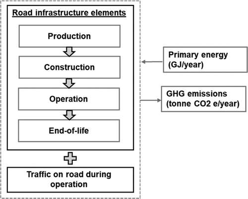
Table A1. User input (project specific data) required to use the LICCER model.
Table 1. Participants at the workshop (not including developers of the LICCER model).
Figure 2. The map shows the location of the three road corridors (Alternative 1, Alternative 2, and Alternative 3) compared in the case study (Englund & Dahlin, 2006). ©Lantmäteriet.
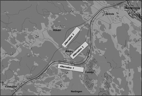
Table A2. Default data of the LICCER model (LICCER_LCA-model_v1 0) used in the case study.
Table A3. Project specific data for infrastructure in the different road corridors (Alt. 1-3) and the reference alternative (Alt. 0).
Table A5. Resulting data inventory for the different life cycle stages of road corridors.
Table A4. Project specific data for current and future traffic operation on the road (common for all road corridors and the reference alternative).
Figure 3. Annual GHG emissions (tonne CO2 equivalents) and energy use (GJ) of infrastructure and traffic in the three road corridors (Alt. 1-Alt.3) and the reference alternative (Alt.0).
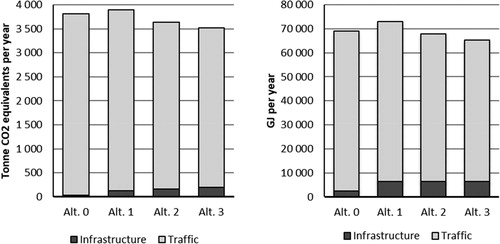
Figure 4. Annual GHG emissions (tonne CO2 equivalents) and energy use (GJ) of infrastructure and traffic in the three road corridors (Alt. 1-Alt.3) and the reference alternative (Alt.0) relative to the reference alternative (ΔAlt.X = Alt.X-Alt.0).
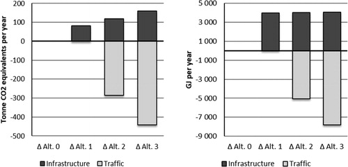
Figure 5. Annual GHG emissions (tonne CO2 equivalents) and energy use (GJ) of infrastructure life cycle stages in the three road corridors (Alt.1-Alt.3) and the reference alternative (Alt.0).
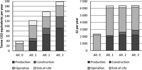
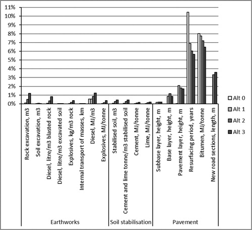
Figure 6. Contribution of construction parts and processes to the annual GHG emissions of each life cycle stage (production, construction, operation, and end-of-life) for the different road corridors (Alt.1-Alt.3) and the reference alternative (Alt.0).
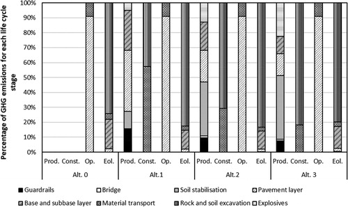
Figure 7. Contribution of construction parts and processes to the annual energy use of each life cycle stage (production, construction, operation, and end-of-life) for the different road corridors (Alt.1-Alt.3) and the reference alternative (Alt.0).
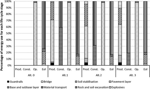
Figure 8. Annual GHG emissions (tonne CO2 equivalents) and energy use (GJ) of different types of vehicles and fuels in the three road corridors (Alt.1-Alt.3) and the reference alternative (Alt.0).
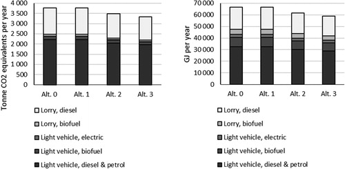
Figure 9. Sensitivity analysis for life cycle GHG emissions of infrastructure.
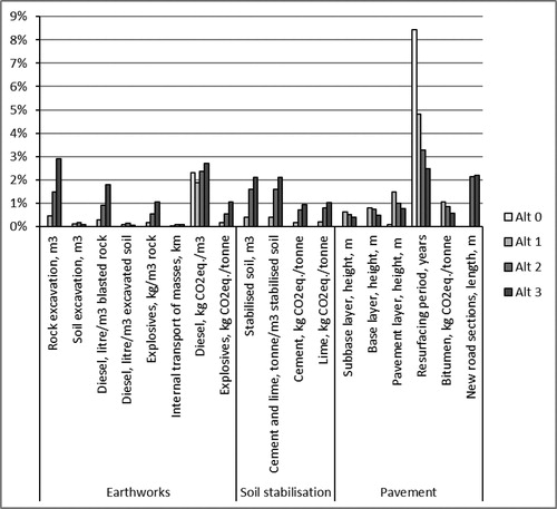
Figure 10. Sensitivity analysis for life cycle energy use of infrastructure.