Figures & data
Figure 1. Typical stairwell door from a historic masonry residential building in Oslo, view from the stairwell side. In this example, the original glass panels have been replaced earlier with wired fire-resistant glass. Photo: Caroline Lundegaard Hannisdal, Murbyen, 2022.
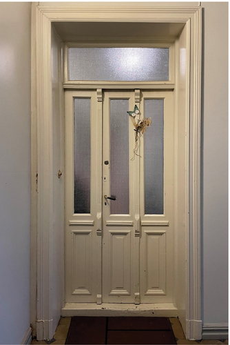
Figure 2. Dimensions of door configurations in mm. Door I was used in test 01A, 01B and 02B. Door II was used in test 03A, 03B, 04A and 04B. Door III was used in test 02A.
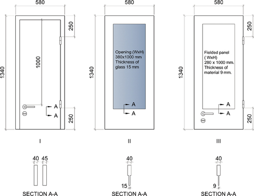
Figure 3. Mounting of fire-resistant glass inside the rebate on the stairwell side (a) of the door or (b) on the apartment side of the door, using steel angles (test 03A and 04A). (c) shows mounting of fire-resistant glass inside the rebate with steel frame on the apartment side of the door (test 03B). (d) shows mounting of fire-resistant glass outside the rebate with steel frame (test 04B).
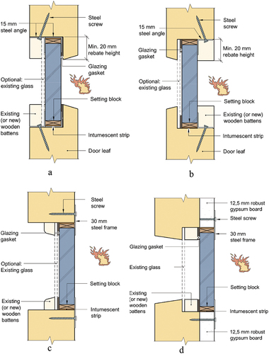
Figure 4. (A) shows a detail of mounting of fire-resistant glass with steel angles and (b) a detail of mounting of 30 mm steel frame.
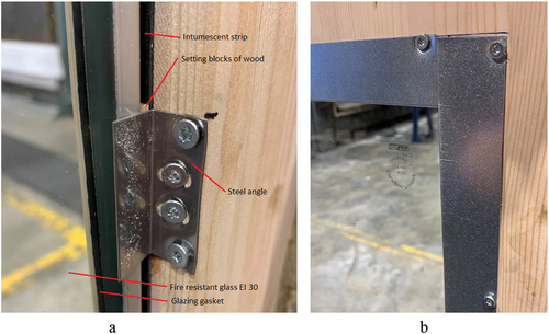
Table 1. Summary of the design of the different door configurations used in the test series.
Figure 5. The fire resistance test furnace used for the tests.
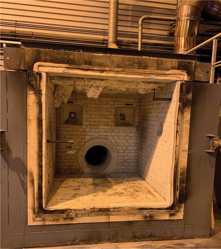
Figure 6. Photo showing positioning of thermocouples on the unexposed side of test specimens 04A and 04B.
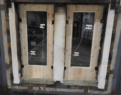
Table 2. Positioning of thermocouples (TC) on the unexposed side of the test specimens, where x = 0 (width), y = 0 (height) marks the bottom left corner of the element as viewed from the unexposed side.
Figure 7. The temperature measurements [°C] as a function of time [minutes] for test specimens (a): 01A (TC1) and 01B (TC2), (b): 02A (TC1-TC2) and 02B (TC3-TC4), (c): 03A (TC1-TC2) and 03B (TC3-TC4), (d): 04A (TC1-TC2) and 04B (TC3-TC4).
![Figure 7. The temperature measurements [°C] as a function of time [minutes] for test specimens (a): 01A (TC1) and 01B (TC2), (b): 02A (TC1-TC2) and 02B (TC3-TC4), (c): 03A (TC1-TC2) and 03B (TC3-TC4), (d): 04A (TC1-TC2) and 04B (TC3-TC4).](/cms/asset/d16efa11-ee97-4646-975b-724e521c8888/uarc_a_2214991_f0007_oc.jpg)
Table 3. Summary of test results measured against the integrity and insulation criteria.
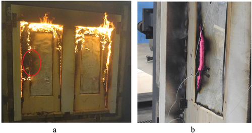
Figure 8. Close ups from the tests (a): 03A/03B after test termination. Cotton wool ignited in the marked area after 29.5 minutes, (b): 04A after 29 minutes, with sustained flaming and failure in temperature criteria.