1,193
Views
13
CrossRef citations to date
0
Altmetric
Short Communication

The AKT2 potassium channel mediates NaCl induced depolarization in the root of Arabidopsis thaliana

Article: e1165381 | Received 22 Feb 2016, Accepted 08 Mar 2016, Published online: 04 Apr 2016

Figures & data

Figure 1. The Electrical Penetration Graph (EPG) rig for recording salt-induced electrical signals in plants. (A) General configuration of the EPG, as set up for this study. The EPG measures the potential difference between a fine intracellular electrode specific for the SE/CC complex (represented by the aphid stylet), and a coarse external copper electrode inserted into the root medium, in this case an aqueous medium. (B) Diagram showing the recording horizons (not to scale) of the intracellular and external EPG electrodes. Since the electrode's recording horizon is positively correlated with the electrode diameter,Citation16 it is reasonable to assume that the large EPG soil electrode (Ø ∼1.5 mm) (electrode B) must be able to detect the electrical activity arising from potentially several cell layers of the area(s) of the root in close proximity, whereas the aphid stylet (electrode A), senses the electrical potential within a small area within the SE/CC complex into which it is inserted – through its watery food and salivary canals with diameters of c. 1 and 0.5 µm, respectively. Electrode A feeds into the non-inverting input of the EPG operational amplifier, whereas electrode B feeds into the inverting input. In this manner, the output of the EPG is the difference between the potentials sensed by electrodes A and B, after reversing the sign of the potential recorded by electrode B. A signal can originate from a potential generated by ionic currents within the recording horizon of electrode A, electrode B, or both.
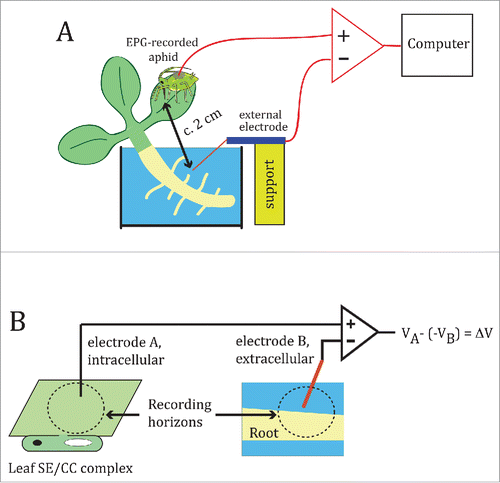
Figure 1. The Electrical Penetration Graph (EPG) rig for recording salt-induced electrical signals in plants. (A) General configuration of the EPG, as set up for this study. The EPG measures the potential difference between a fine intracellular electrode specific for the SE/CC complex (represented by the aphid stylet), and a coarse external copper electrode inserted into the root medium, in this case an aqueous medium. (B) Diagram showing the recording horizons (not to scale) of the intracellular and external EPG electrodes. Since the electrode's recording horizon is positively correlated with the electrode diameter,Citation16 it is reasonable to assume that the large EPG soil electrode (Ø ∼1.5 mm) (electrode B) must be able to detect the electrical activity arising from potentially several cell layers of the area(s) of the root in close proximity, whereas the aphid stylet (electrode A), senses the electrical potential within a small area within the SE/CC complex into which it is inserted – through its watery food and salivary canals with diameters of c. 1 and 0.5 µm, respectively. Electrode A feeds into the non-inverting input of the EPG operational amplifier, whereas electrode B feeds into the inverting input. In this manner, the output of the EPG is the difference between the potentials sensed by electrodes A and B, after reversing the sign of the potential recorded by electrode B. A signal can originate from a potential generated by ionic currents within the recording horizon of electrode A, electrode B, or both.

Figure 2. Electrophysiological responses of wild type Arabidopsis thaliana and Azolla filiculoides to root salt application. (A, B) Electrical potentials generated between the SE/CC-intracellular electrode and the root-external electrode of the EPG, in response to application of increasingly higher concentrations of NaCl (1, 10, 50 and 100 mM) in an A. thaliana (A) and in an A. filiculoides plant (B). Before applying 10, 50 or 100 mM NaCl, the effects of the previous salt concentration were washed out by replacing the NaCl solution with distilled water, as shown in (C). (D), Comparison between the averaged maximum depolarizations of A. thaliana and A. filiculoides as a function of NaCl concentration. Data points represent mean ± s.e.m. Numbers in parentheses indicate the number of plants per NaCl concentration. (E), Electrical potential triggered by application of 100 mM KCl to the root of A. thaliana, and its reversibility by washout.
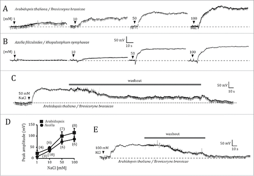
Figure 2. Electrophysiological responses of wild type Arabidopsis thaliana and Azolla filiculoides to root salt application. (A, B) Electrical potentials generated between the SE/CC-intracellular electrode and the root-external electrode of the EPG, in response to application of increasingly higher concentrations of NaCl (1, 10, 50 and 100 mM) in an A. thaliana (A) and in an A. filiculoides plant (B). Before applying 10, 50 or 100 mM NaCl, the effects of the previous salt concentration were washed out by replacing the NaCl solution with distilled water, as shown in (C). (D), Comparison between the averaged maximum depolarizations of A. thaliana and A. filiculoides as a function of NaCl concentration. Data points represent mean ± s.e.m. Numbers in parentheses indicate the number of plants per NaCl concentration. (E), Electrical potential triggered by application of 100 mM KCl to the root of A. thaliana, and its reversibility by washout.

Figure 3. Electrophysiological responses of akt1 and akt2 mutants of Arabidopsis thaliana to NaCl root application. Electrical potentials induced by 50 mM NaCl to the root of akt1 (A) and akt2 (B). (C), Plot of the averaged maximum depolarization levels as a function of NaCl concentration for the wild type, and the akt1 and akt2 mutants. Data points represent mean ± s.e.m. Numbers in parentheses indicate the number of plants per NaCl concentration. Only one NaCl concentration per plant was tested. Whenever plants were exposed to several NaCl concentrations, a given NaCl solution was only applied after the effects of the previous NaCl solution had been completely washed out by manual solution exchange.
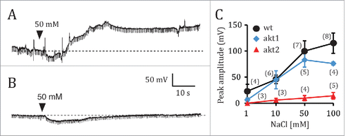
Figure 3. Electrophysiological responses of akt1 and akt2 mutants of Arabidopsis thaliana to NaCl root application. Electrical potentials induced by 50 mM NaCl to the root of akt1 (A) and akt2 (B). (C), Plot of the averaged maximum depolarization levels as a function of NaCl concentration for the wild type, and the akt1 and akt2 mutants. Data points represent mean ± s.e.m. Numbers in parentheses indicate the number of plants per NaCl concentration. Only one NaCl concentration per plant was tested. Whenever plants were exposed to several NaCl concentrations, a given NaCl solution was only applied after the effects of the previous NaCl solution had been completely washed out by manual solution exchange.

Reprints and Corporate Permissions

Please note: Selecting permissions does not provide access to the full text of the article, please see our help page How do I view content?

To request a reprint or corporate permissions for this article, please click on the relevant link below:

Academic Permissions

Please note: Selecting permissions does not provide access to the full text of the article, please see our help page How do I view content?

Obtain permissions instantly via Rightslink by clicking on the button below:

If you are unable to obtain permissions via Rightslink, please complete and submit this Permissions form. For more information, please visit our Permissions help page.