523
Views
4
CrossRef citations to date
0
Altmetric
Original Articles

A Decentralized Robust PID Controller Design for the Shape Control of a Magnetic Fluid Deformable Mirror

, &
Pages 246-268 | Published online: 15 Sep 2010

Figures & data

Figure 1 Operating principle of an adaptive optics system. In this setup, the deformable mirror shape is adjusted so that the wavefront shape of the beam reflecting off the deformable mirror surface matches a desired shape stored in the controller. (Figure is provided in color online.).
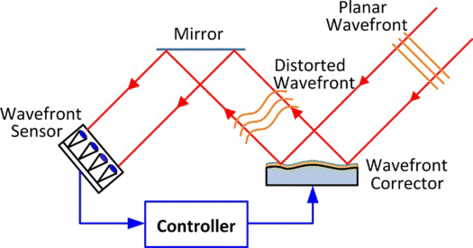
Figure 1 Operating principle of an adaptive optics system. In this setup, the deformable mirror shape is adjusted so that the wavefront shape of the beam reflecting off the deformable mirror surface matches a desired shape stored in the controller. (Figure is provided in color online.).

Figure 2 Block diagram of the closed-loop adaptive optics system experimental setup. (Figure is provided in color online.).
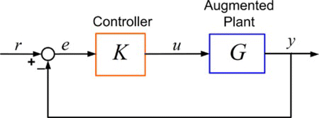
Figure 2 Block diagram of the closed-loop adaptive optics system experimental setup. (Figure is provided in color online.).

Figure 3 Bode plot of the MFDM. The array of Bode plots shows the system response for channels corresponding to three inputs and three outputs selected in a radial direction. The plots on the diagonal correspond to collocated input-output pairs. (Figure is provided in color online.).
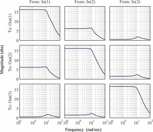
Figure 3 Bode plot of the MFDM. The array of Bode plots shows the system response for channels corresponding to three inputs and three outputs selected in a radial direction. The plots on the diagonal correspond to collocated input-output pairs. (Figure is provided in color online.).

Figure 4 Block diagram of the closed-loop system showing the system . (Figure is provided in color online.).
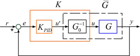
Figure 4 Block diagram of the closed-loop system showing the system . (Figure is provided in color online.).

Figure 5 Bode plot of the DC decoupled MFDM system. The system is DC decoupled by pre-multiplying it with the inverse of its DC gain. (Figure is provided in color online.).
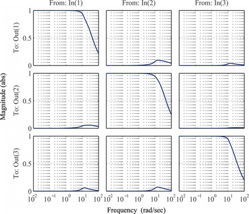
Figure 5 Bode plot of the DC decoupled MFDM system. The system is DC decoupled by pre-multiplying it with the inverse of its DC gain. (Figure is provided in color online.).

Figure 6 Bode plots of and that of a typical diagonal entry in . (Figure is provided in color online.).
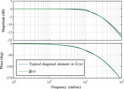
Figure 6 Bode plots of and that of a typical diagonal entry in . (Figure is provided in color online.).

Figure 7 Block diagram of the closed-loop system with the uncertain plant model. (Figure is provided in color online.).
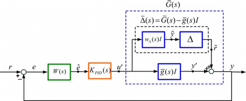
Figure 7 Block diagram of the closed-loop system with the uncertain plant model. (Figure is provided in color online.).

Figure 8 Block diagram of the reconfigured closed loop system showing the blocks Δ and Σ. (Figure is provided in color online.).
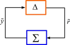
Figure 8 Block diagram of the reconfigured closed loop system showing the blocks Δ and Σ. (Figure is provided in color online.).

Figure 9 Layout of the experimental setup (L: lens, M: mirror, R: relay, BS: beam-splitter, all dimensions are in mm). The items in dotted blue lines are needed only for retinal imaging applications. (Figure is provided in color online.).
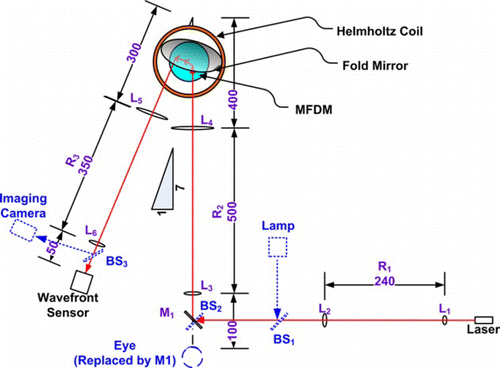
Figure 9 Layout of the experimental setup (L: lens, M: mirror, R: relay, BS: beam-splitter, all dimensions are in mm). The items in dotted blue lines are needed only for retinal imaging applications. (Figure is provided in color online.).

Figure 10 Experimental tracking of the static reference shape using the decentralized PID controller. (Figure is provided in color online.).
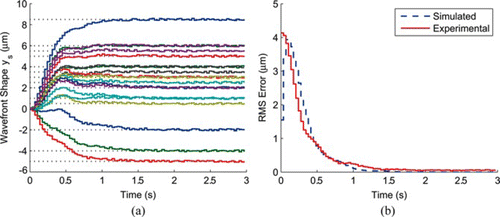
Figure 10 Experimental tracking of the static reference shape using the decentralized PID controller. (Figure is provided in color online.).

Figure 11 Contour plot of the error surface in µm. (a) Before correction (b) After correction. (Figure is provided in color online.).
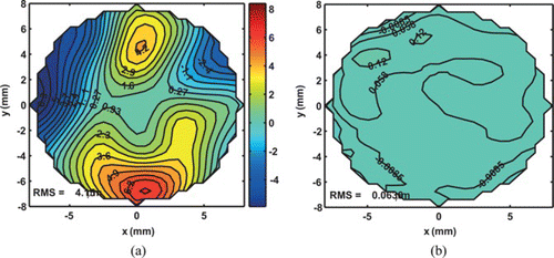
Figure 11 Contour plot of the error surface in µm. (a) Before correction (b) After correction. (Figure is provided in color online.).
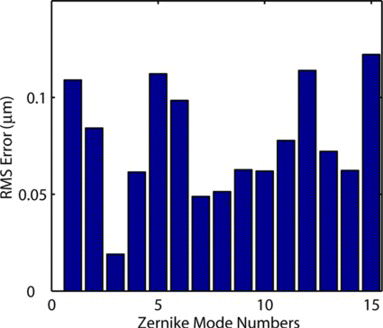
Figure 12 Zernike mode shapes generated using the MFDM (in µm): (a) acquired, (b) desired shapes (c) error surface. (Figure is provided in color online.).

Figure 12 Zernike mode shapes generated using the MFDM (in µm): (a) acquired, (b) desired shapes (c) error surface. (Figure is provided in color online.).

Figure 13 RMS error for the Zernike mode shapes experimentally generated using the MFDM. (Figure is provided in color online.).

Figure 13 RMS error for the Zernike mode shapes experimentally generated using the MFDM. (Figure is provided in color online.).

Reprints and Corporate Permissions

Please note: Selecting permissions does not provide access to the full text of the article, please see our help page How do I view content?

To request a reprint or corporate permissions for this article, please click on the relevant link below:

Academic Permissions

Please note: Selecting permissions does not provide access to the full text of the article, please see our help page How do I view content?

Obtain permissions instantly via Rightslink by clicking on the button below:

If you are unable to obtain permissions via Rightslink, please complete and submit this Permissions form. For more information, please visit our Permissions help page.