582
Views
16
CrossRef citations to date
0
Altmetric
Regular Articles

An Automatic Inspection Method for the Fracture Conditions of Anisotropic Conductive Film in the TFT-LCD Assembly Process

, , , &
Pages 286-298 | Published online: 21 Sep 2011

Figures & data

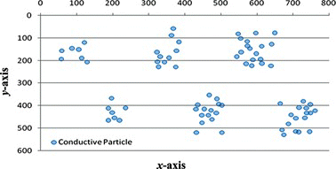
Figure 1 (a) Distribution diagram of conducting particles inside sealing ACF. (b) Diagram of the structure of conducting particles inside the ACF and particle distribution inside the film (color figure available online).
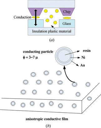
Figure 1 (a) Distribution diagram of conducting particles inside sealing ACF. (b) Diagram of the structure of conducting particles inside the ACF and particle distribution inside the film (color figure available online).

Figure 2 (a) The ACF image and the coordinate systems. (b) Prewitt mask operator. (c) 3 × 3 regional image (color figure available online).
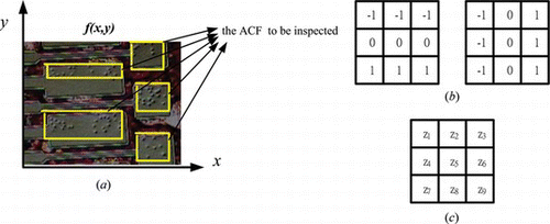
Figure 2 (a) The ACF image and the coordinate systems. (b) Prewitt mask operator. (c) 3 × 3 regional image (color figure available online).

Figure 3 Relations of conducting particle shape, conditions and its deformation (color figure available online).
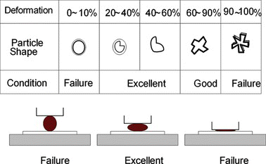
Figure 3 Relations of conducting particle shape, conditions and its deformation (color figure available online).

Figure 4 (a) ACF inspection image. (b) Target template. (c) Comparison result of block target template. (d) Comparison result of conducting particles (color figure available online).
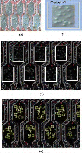
Figure 4 (a) ACF inspection image. (b) Target template. (c) Comparison result of block target template. (d) Comparison result of conducting particles (color figure available online).

Figure 5 (a) ACF inspection image of the conducting particles distributed in diversified blocks. (b) Settings for complex template. (c) Result display of synchronous comparison of complex template (color figure available online).
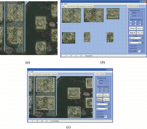
Figure 5 (a) ACF inspection image of the conducting particles distributed in diversified blocks. (b) Settings for complex template. (c) Result display of synchronous comparison of complex template (color figure available online).

Figure 6 (a) Image pretreatment series (1). (b) Image pretreatment series (2). (c) Pretreatment of conducting particle image (color figure available online).
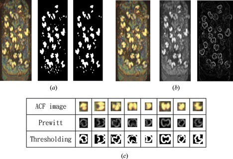
Figure 6 (a) Image pretreatment series (1). (b) Image pretreatment series (2). (c) Pretreatment of conducting particle image (color figure available online).
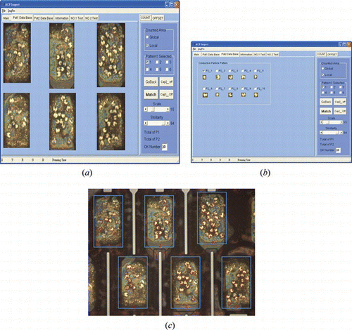
Figure 7 Skeletonization treatment scheme (color figure available online).

Figure 7 Skeletonization treatment scheme (color figure available online).

Figure 8 (a) Set Bump block template image. (b) Set selection of conducting particle image template. (c) Comparison result of fracture characteristics of ACF conducting particles (color figure available online).

Figure 8 (a) Set Bump block template image. (b) Set selection of conducting particle image template. (c) Comparison result of fracture characteristics of ACF conducting particles (color figure available online).

Figure 9 Result of ACF conducting particles distribution (color figure available online).

Figure 9 Result of ACF conducting particles distribution (color figure available online).

Reprints and Corporate Permissions

Please note: Selecting permissions does not provide access to the full text of the article, please see our help page How do I view content?

To request a reprint or corporate permissions for this article, please click on the relevant link below:

Academic Permissions

Please note: Selecting permissions does not provide access to the full text of the article, please see our help page How do I view content?

Obtain permissions instantly via Rightslink by clicking on the button below:

If you are unable to obtain permissions via Rightslink, please complete and submit this Permissions form. For more information, please visit our Permissions help page.