1,398
Views
5
CrossRef citations to date
0
Altmetric
Original Articles

Integration of Optical Manipulation and Electrophysiological Tools to Modulate and Record Activity in Neural Networks

, , &
Pages 191-216 | Published online: 21 Sep 2011

Figures & data

Figure 1 Schematic optical layout of the instrument (color figure available online).

Figure 1 Schematic optical layout of the instrument (color figure available online).

Figure 2 Schematic and physical optical layout of the instrument (color figure available online).

Figure 2 Schematic and physical optical layout of the instrument (color figure available online).

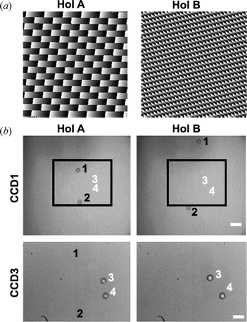
Figure 3 Double objective holographic tweezers.

Figure 3 Double objective holographic tweezers.

Figure 4 Holographic trapping on non-transparent substrates.

Figure 4 Holographic trapping on non-transparent substrates.

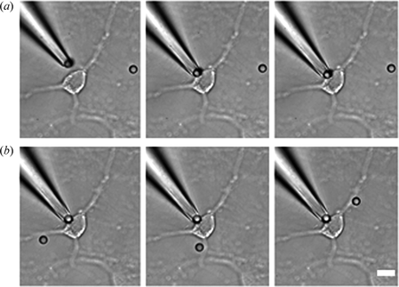
Figure 5 Simultaneous manipulation of beads in the vicinity of a neuron by a pipette and OTs.

Figure 5 Simultaneous manipulation of beads in the vicinity of a neuron by a pipette and OTs.

Figure 6 Concerted and independent optical trapping of silica beads on MEAs.

Figure 6 Concerted and independent optical trapping of silica beads on MEAs.

Table 1. Feature comparison of different water-dipping objectives for optical trapping

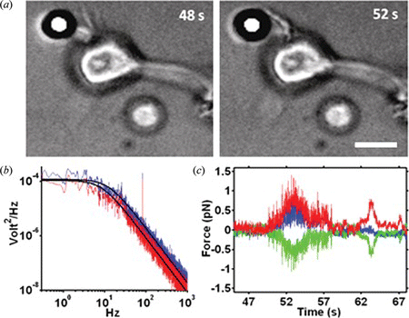
Figure 7 Force spectroscopy measurement on an individual neuron (color figure available online).

Figure 7 Force spectroscopy measurement on an individual neuron (color figure available online).

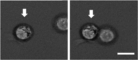
Figure 8 Arranging cells with optical tweezers.

Figure 8 Arranging cells with optical tweezers.

Figure 9 Calcium imaging of shock wave propagation induced by laser dissection on a random neural network plated on a MEA (color figure available online).
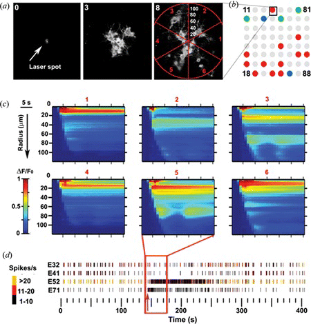
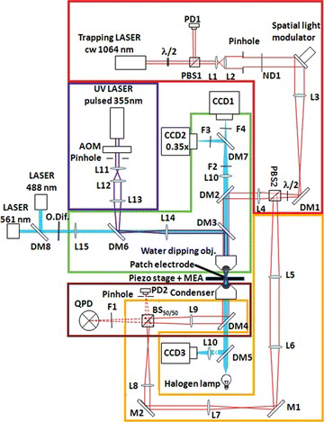
Figure 9 Calcium imaging of shock wave propagation induced by laser dissection on a random neural network plated on a MEA (color figure available online).
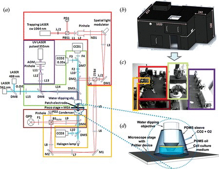
Table 2. Pros and cons of distinct optical microscope systems. Shaded boxes indicate the available components in the setup in Figure

Table 3. Pros and cons of distinct optical tweezers systems. Shaded boxes indicate the available components in the setup in Figure

Table 4. Pros and cons of distinct laser microdissector systems. Shaded boxes indicate the available components in the setup in Figure

Table 5. Pros and cons of distinct electrophysiological recording systems. Shaded boxes indicate the available components in the setup in Figure

Reprints and Corporate Permissions

Please note: Selecting permissions does not provide access to the full text of the article, please see our help page How do I view content?

To request a reprint or corporate permissions for this article, please click on the relevant link below:

Academic Permissions

Please note: Selecting permissions does not provide access to the full text of the article, please see our help page How do I view content?

Obtain permissions instantly via Rightslink by clicking on the button below:

If you are unable to obtain permissions via Rightslink, please complete and submit this Permissions form. For more information, please visit our Permissions help page.