843
Views
11
CrossRef citations to date
0
Altmetric
Original Articles

Correction of Errors in Polarization Based Dynamic Phase Shifting Interferometers

Figures & data

Figure 1 General ellipse plot showing the parametric angle, θ, the coordinate angle, θ′, and the difference angle, ϵ =θ′–θ, for a given point {D, N}.
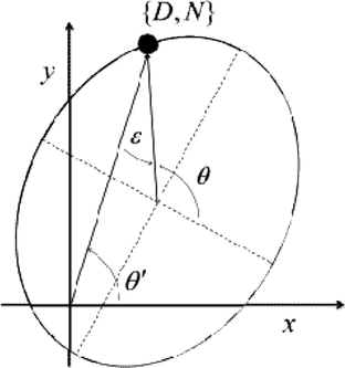
Figure 1 General ellipse plot showing the parametric angle, θ, the coordinate angle, θ′, and the difference angle, ϵ =θ′–θ, for a given point {D, N}.

Figure 2 (a) Lissajous plots associated with offset, amplitude, and phase errors where coordinate points given by parametric Equations 2 and 3. (b) Phase calculation error given by the difference between the coordinate and parametric angle of each point in the curves of Figure 2(a).
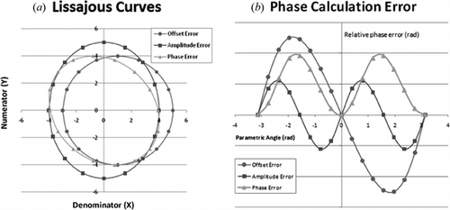
Figure 2 (a) Lissajous plots associated with offset, amplitude, and phase errors where coordinate points given by parametric Equations 2 and 3. (b) Phase calculation error given by the difference between the coordinate and parametric angle of each point in the curves of Figure 2(a).

Figure 3 Phase measurement process. (a) On each measurement an interferometer returns two interferograms, each phase shifted approximately 90 degrees with respect to the other. A series of six measurements are made where a phase offset is introduced between the measurements. (b) For a single pixel, highlighted red box, all {D, N} pairs are plotted forming an offset ellipse as shown. From these points a best fit ellipse is determined. C. Using the ellipse fit coefficients, all {D, N} pairs are transformed to lie on a circle centered at the origin. The phase at each point is given by the arctangent of the ratio of the Nt to Dt terms. Steps B. and C. are repeated for all points in the field.
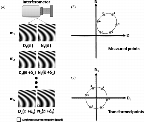
Figure 3 Phase measurement process. (a) On each measurement an interferometer returns two interferograms, each phase shifted approximately 90 degrees with respect to the other. A series of six measurements are made where a phase offset is introduced between the measurements. (b) For a single pixel, highlighted red box, all {D, N} pairs are plotted forming an offset ellipse as shown. From these points a best fit ellipse is determined. C. Using the ellipse fit coefficients, all {D, N} pairs are transformed to lie on a circle centered at the origin. The phase at each point is given by the arctangent of the ratio of the Nt to Dt terms. Steps B. and C. are repeated for all points in the field.

Figure 4 Comparison of phase calculation errors for a high numerical aperture system. The top figures show the measurement error, both areal and cross section, when using the standard algorithm. The middle figures provided the resulting error when a flat field correction is applied. The bottom figures show the effect of the ellipse to circle, E2C correction on the measurement error.
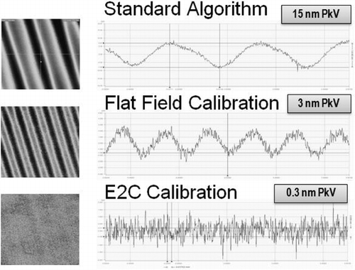
Figure 4 Comparison of phase calculation errors for a high numerical aperture system. The top figures show the measurement error, both areal and cross section, when using the standard algorithm. The middle figures provided the resulting error when a flat field correction is applied. The bottom figures show the effect of the ellipse to circle, E2C correction on the measurement error.
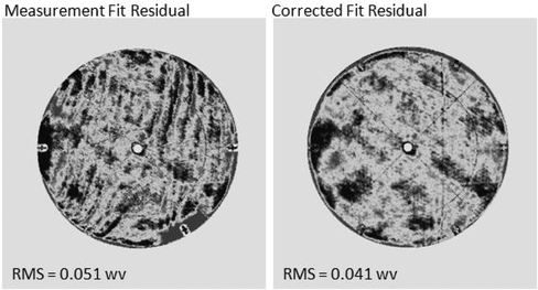
Figure 5 Print-through correction on a cryo-tested convex hyperboloid. Measurement residuals resulting from the removal of a 32 term Zernike fit shown.

Figure 5 Print-through correction on a cryo-tested convex hyperboloid. Measurement residuals resulting from the removal of a 32 term Zernike fit shown.

Reprints and Corporate Permissions

Please note: Selecting permissions does not provide access to the full text of the article, please see our help page How do I view content?

To request a reprint or corporate permissions for this article, please click on the relevant link below:

Academic Permissions

Please note: Selecting permissions does not provide access to the full text of the article, please see our help page How do I view content?

Obtain permissions instantly via Rightslink by clicking on the button below:

If you are unable to obtain permissions via Rightslink, please complete and submit this Permissions form. For more information, please visit our Permissions help page.