
Figures & data
Figure 1. Sorting mechanisms. (a-d) Optical field distributions of 2-dimensional (2D) Airy beams in x-y and x-z planes with different inner radii () and direction angles (θ). (a)
= 0.2, θ = −0.25π; (b)
= 0.2, θ = 0.25π; (c)
= 0.2, θ = 0.75π; (d)
= 0.5, θ = 0.25π. (e) Calculated FS exerted on PS particles as functions of H. (f, g) Calculated intensity distributions of the Airy beam after refraction from PS particles (marked by white rings) with diameters of (f) 2 μm and (g) 4 μm.
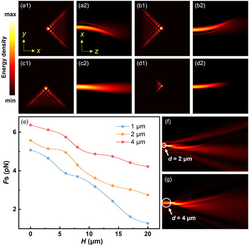
Figure 2. Experiment design. (a) Schematic of the experimental setup of the holographic optical tweezer system. Laser: continuous wave 1064 nm laser; P: polarizer; L1, L2: plano-convex lenses; M1, M2: mirrors; SLM: spatial-light modulator; L3, L4: relay lenses; TL: tube lens; DM1, DM2: dichroic mirrors; O: objective; S: stage; C: condenser; DIA LED: diascopic illumination; CMOS: camera. (b, c) Propulsion distances in (b) axial (ΔH) and (c) lateral (ΔX) directions at different laser powers for PS particles with diameters of 1, 2 and 4 μm. (d) Motion of PS particles of different sizes under the action of the Airy beam with varying inner radius (r˜). (e) Airy beam trapping stiffness of 4 μm PS particles at different laser powers with r˜ = 0.5.
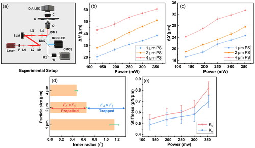
Figure 3. Selective clearing and size-based sorting. (a1) A 4 μm particle being trapped by the Airy beam with an inner radius () of 0.5 while a 2 μm propelled by the same Airy beam. (a2-a4) Selective clearing of 2 μm particles from a mixture of 2 μm and 4 μm particles. (b1) Six PS particles with diameters of 1 μm, 2 μm, and 4 μm randomly distributed within the trapping region of the HOT. (b2-b4) Particles with diameters of 2 μm, 1 μm, and 4 μm distributed at (b2) ΔH = 0, (b3) ΔH1 = 20 μm, and (b4) ΔH2 = 43 μm, respectively, after sorting by the transition from Gaussian beams to Airy beams.
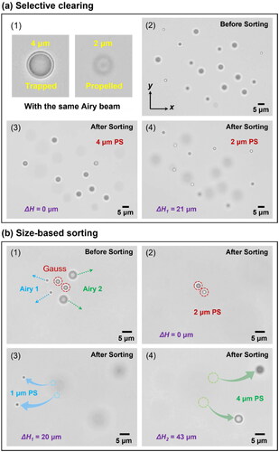
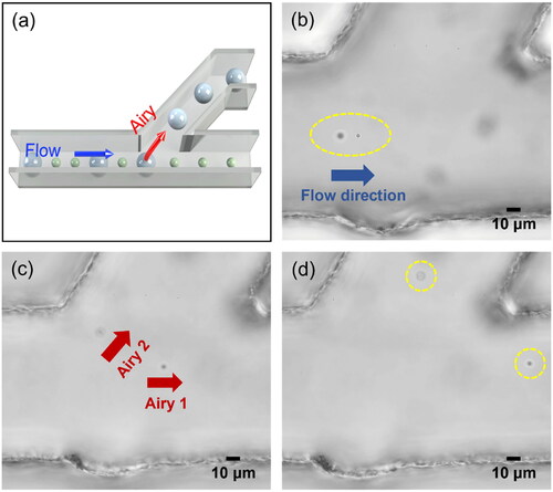
Figure 4. Optofluidic sorting in microfluidic system. (a) Schematic of optofluidic sorting of 2 μm and 4 μm PS particles. (b, c) 2 μm and 4 μm particles were propelled into different heights and directions with = 0.5, θ = 0.25π and
= 0.2, θ = 0.5π, respectively. (d) The 2 μm and 4 μm particles were sorted into the top and bottom channels, respectively.